
User Manual

6
© Copyright 2011. All rights reserved.
Section 1: Media Filter (Gravity) Installation Instructions
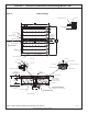
1. Excavate a hole for the media lter, large enough to build the liner
support walls. NOTE: Support walls should extend a minimum of
4” above the original grade to allow surface water to be diverted
away from the media lter.
2. Excavate a trench for the supply piping and for the drain piping
to the media lter.
3. Smooth, rake, compact and level the bottom of the excavation
as required. If additional leveling material is required, use the
media/gravel material.
4. Erect the support walls of approved material and size. Pressure
treated 2x10’s or concrete are recommended.
5. Using a 4½” hole saw, locate and cut a hole in the wall for the
drainpipe penetration. The hole should be horizontally centered
on the wall being penetrated and the edge should be within ½”
of the bottom grade of the lter.
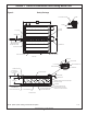
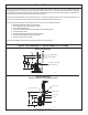
6. Using a 2” hole saw, locate and cut a hole in the wall for the supply
pipe penetration. The hole should be horizontally centered on
the wall being penetrated and the edge should be 1½” above the
24” of lter media or 26½” to the center line of the 2” hole from
the underdrain media (see Figure 2 on page 5).
7. Install the protective mat.
8. Install the liner, making bottom and corners smooth. Excess
should be laid over the top and tucked down the outside of support
walls.
9. Using a utility knife, cut a hole through the liner to match the 4½”
and 2” holes cut in the support walls.
10. Clean the area on the liner around the drain supply penetration
holes with Firestone Quick Prime Plus. Apply the primer with a
scrubber pad or clean cotton rag. Thoroughly scrub the bonding
area three times with primer. Allow the primer to dry for 10
minutes. Remove the protective paper from seal boot adhesive.
Do not touch the adhesive surface. Place boot adhesive against
cleaned and smoothed liner surface. Press the boot with a roller
or acceptable tool to ensure bubbles and wrinkles are removed.
DO NOT PEEL BOOT BACK TO TEST SEAL.
11. Slide the 4” penetration pipe into the discharge seal boot. The
seal boot may need to be trimmed to the appropriate diameter.
The boot should t snug with no wrinkles.
12. Place the hose clamp around the boot onto 4” penetration pipe
and tighten. Apply a bead of Firestone lap sealant caulk where
the pipe boot meets the pipe.
13. Attach the 4” pipe cap or screened vent riser to the opposite end
of the drainpipe.
14. Cut the drainpipe to required length and attach it to the penetration
pipe using the 4” coupling. (Drainpipe should extend as close as
possible to opposite support wall).
15. Slide the 1¼” penetration pipe into the inlet seal boot. The seal
boot may need to be trimmed to the appropriate diameter. The
boot should t snug with no wrinkles.
16. Place the hose clamp around the boot onto 1¼” penetration pipe
and tighten. Apply a bead of Firestone lap sealant caulk where
the pipe boot meets the pipe.
17. Install 8” of the appropriate underdrain media (¾” to 1½” gravel
typical). While lling, be sure to position the drainpipe properly.
Backll 8” with the excavated material outside the frame as you
ll inside the frame.
18. Install 24” of the specied ltering media. Backll 24” with the
excavated material outside the frame as you ll the inside the
frame.
19. Install 1½” of the appropriate overlay media (¾” to 1½” gravel
typical).
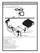
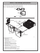
20. Place manifold and distribution piping on overlay media. Remove
the protector plugs from the manifold and the distribution pipes
as installing.
21. Attach the manifold to the supply penetration pipe making sure
that the “T” tting points in the correct direction.
22. Attach the distribution pipes to the manifold ensuring the elbow
end is vertically plumb, with clean out pointing up.
23. Snap the orice shields over the holes in the bottom of the
distribution pipes.
24. Slide the risers over the clean outs (90° sweep elbow). Place
appropriate overlay media (¾” to 1½” gravel typical) around risers
to hold them in place.
25. Install 3” to 4½” of the appropriate overlay media (3/8” to 1”
gravel typical). While lling, be sure the discharge pipes stay
positioned.
26. Install a protective buried fence (optional).
27. Install 3” of the appropriate overlay media (¾” to 1½” gravel
typical). A maximum of 8” of overlay media is allowed above the
discharge pipes.
28. Make nal supply and drain connections if this has not already
been done.
29. Finish by backlling and landscaping. Be sure there is a 4”
(minimum) berm surrounding the media lter to ensure that no
surface water enters the media lter system.