
Owner's manual

10
© Copyright 2012. All rights reserved.
P R E L I M I N A RY
The recirculation ow is designed to be 1.2-1.8 times that
of the average design inow. Table 4 indicates starting
ow rates for each unit. However, ne adjustments may be
necessary to ensure optimum performance.
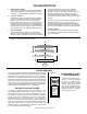
Setting the ow rate:
• Adjust the ow using rates in Table 4.
• The ow rate is adjusted by rotating the gray recirculation
valve (2) and observing the ow at the pipe end.
• There are prescribed lines at the outlet of the recirculation
pipe to aid in approximating the correct ow.
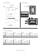
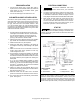
Measuring the ow rate:
• The actual ow rates must be measured to verify ow
after adjustment of the valve and observation at the
pipe end.
• Measure the time in seconds required to ll a 1L
container.
• Compare the time to value ranges in Table 4.
• If necessary, adjust the valve again and collect another
sample to verify the correct ow rates.
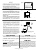
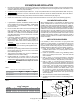
In order to prevent plugging of the media in the Aeration
Chamber, the backwash cycle activates at a preset
schedule. If there is no backwash cycle or too short
of a backwash cycle, the unit’s performance will be
adversely affected. Likewise, if the backwash cycle is
too long, performance will be compromised.
The backwash cycle begins at 2:00 AM and lasts for ve
minutes. One hour later, another ve minute backwash
cycle occurs. Even with these default settings, the waste
water inow could be too low or too high to optimize
the performance and therefore, must be checked during
each inspection. The backwash initiation time can be
set for any time during a
24-hour period to accomodate unusual water use
patterns. The goal is to set the time when there is no
ow into the unit.
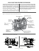
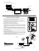
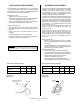
The backwash cycle and sludge transfer from the
Aeration Chamber takes place at the same time.
Verify that the air ow is uniform across the Aeration
Chamber between the two sides during a backwash
cycle. If not, adjust the red backwash valve (3)
accordingly.
Setting the ow rate:
• Switch to a manual backwash cycle by pressing
the pink "Manual Backwash" button on the blower
control pad.
• Set the backwash ow rate by adjusting the gray
sludge transfer valve (4). Use Table 5 to determine
the setting for each Fusion
®
model.
Measuring the ow rate:
• Measure the actual backwash ow rate at the
outlet of the sludge return pipe in the rst chamber
the same way the recirculation ow rate is measured.
• Adjust the gray sludge transfer valve (4) if
necessary to obtain the proper ow.
• Return the blower to normal aeration mode by
pressing the pink button on the blower's control pad.
It is important not to set the flow rate too high
because it can cause excessive agitation within the first chamber
(Sedimentation Chamber). This could result in poor performance.
RECIRCULATION FLOW ADJUSTMENT
BACKWASH FLOW ADJUSTMENT
Table 5 - Backwash Flow Rate Setting
Model Frequency ZF450 ZF600 ZF800
Backwash ow rate
(sec/liter)
Twice/day 7-10 5-7 4-6
Valve open (%) Twice/day 50-55 40-45 40-45
Figure 15 - Flow
Controlling Valve
Figure 14 - Flow
Measurement
Model ZF450 ZF600 ZF800
Recirculating ow rate
(sec/liter)
29-45 21-32 14-22
Suggested Valve Opening 35-40% 30-35% 30-35%
Table 4 - Recirculation Flow Rates
DOTTED
SCALE
VALVES
SUGGESTED
RANGE
MARKER
CONTAINER
RECIRCULATION OR
BACKWASH PIPE