
Manual


3
© Copyright 2013. All rights reserved.
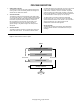
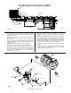
Back-Wash
Recirculation
Sedimentation Chamber
Anaerobic Chamber
Aeration Chamber
Storage Chamber
Effluent
Inflow
1
2
3
4
Figure 3 - Treatment Flow of the Fusion
®
System.
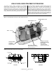
PROCESS DESCRIPTION
1. Sedimentation Chamber
This chamber is designed to physically separate solids from the
incoming water. Scum is the oating material and sludge is the
material that has settled at the bottom.
2. Anaerobic Chamber
This chamber contains a spherical skeleton-type of lter media,
4.3 inch diameter (109 mm). Through bacterial growth processes
on the surface of the lter media, biological anaerobic treatment
thrives while suspended solids are captured. Furthermore,
the microorganisms in this chamber convert nitrates in the
recirculated water returning from the aerobic chamber to
gaseous nitrogen. The gaseous nitrogen then escapes to the
atmosphere.
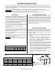
3. Aeration Chamber
The aeration chamber consists of an aerated upper section and
a lter media lower section. The chamber is lled with hollow,
cylindrical lter media 0.6 inch diameter (15 mm) and 0.55 inches
long (14 mm). Biological treatment takes place on the lter
media surface. Aeration is continuous. Residual suspended
solids are captured by the lter media circulating in this section.
During normal operation, a recirculation line transfers water back
to the sedimentation chamber by way of an air lift pump.
The lter media in the aeration chamber are backwashed
regularly (twice a day, 5 or 10 minute cycle) by the backwash
system located at the bottom of the chamber. The accumulated
sludge is transferred by an air lift pump back into the
sedimentation chamber for further digestion.
4. Storage Chamber
This chamber is designed to temporarily store treated water
exiting the aeration chamber. This treated water is ready for
discharge.