
User guide
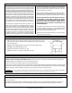

4
© Copyright 2014. All rights reserved.
4
1
3
6
5
2
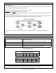
Parts List
REF NO. DESCRIPTION PART NO.
1
Two zone for four or six outlet valve 153276
Three zone cam for four outlet valve 019586
Four zone cam for four outlet valve 019938
Three zone cam for six outlet valve 153277
Four zone cam for six outlet valve 153278
Five zone cam for six outlet valve 153279
Six zone cam for six outlet valve 152185
2
Stem / disk assy. w/ .028 spring (white) 151236
Light stem / disk assy. w/ .025 spring (blue) 152518
Heavy stem / disk assy. w/ .032 spring (red) 153280
3 Valve top retaining screw set (7)(10x1 Phil Pan SS) 153281
4 Cam retaining screw set (2)(10-24x3/4 Phil Pan SS) 153282
5 Valve Top O-ring 153283
6 Cam O-ring 153284
Parts List
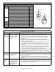
Troubleshooting and Service Checklist
Problem Cause Solution
Valve does
not change or
cycle to next
zone or outlet.
The stem and disk as-
sembly is not rotating
when the water ow is
turned OFF and then
back ON.
• Ensure there is no debris inside the cam. Clean and carefully reinstall the cam.
• If fewer than the maximum number of outlets are being used, check the
installation of the cam. Ensure that the stem and disk assembly is not being
held down by an improperly installed cam. Refer to the Cam Replacement
Instructions.
• Remove the valve top and check for proper movement of stem and disk
assembly. Check for and remove any debris or foreign objects that may jam or
retard the movement of the disk.
• Check for freedom of movement of stem and disk assembly up and down over
the center pin in bottom of valve. Scale deposits may build up on the pin and
hold stem and disk assembly down. Clean pin and again check for freedom of
movement.
• Be sure that all operating outlets are not capped and that the ow to operating
zones is not restricted in any manner. This would cause pressure to build up in
the valve and lock the stem and disk assembly in the down position.
• The back ow of water from uphill lines may be preventing the valve from cycling
properly. If the valve cannot be placed close to the high point of the system, a
check valve should be installed near the valve in the outlet line that runs uphill
from the valve.
Water comes
out of all the
valve outlets.
Stem and disk assembly
not seating properly on
valve outlet.
• Check for sufcient water ow. A minimum of 10 GPM is required to properly seat
the disk. For water ow between 6 and 10 GPM, a stem and disk assembly with a
lighter spring is available.
• Remove the valve top and check the inside walls to ensure that nothing is
interfering with the up and down movement of the stem and disk assembly inside
the valve.
Valve skips
outlets or
zones.
This will cause the valve
to cycle quickly several
times, skipping one or
more zones. The ow
should be steady and
uninterrupted.
• The stem and disk assembly is being advanced past the desired outlet.
• Ensure that the correct cam for the desired number of zones is installed and that
the outlet lines are installed to the correct outlet ports of the valves as indicated
by the zone numbers on the top of the cam.