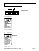
E Operator's Manual ENCORE S2426/L2426 READ THIS BOOK CAUTION: Read the Operator's Manual before using the appliance. This book has important information for the use and safe operation of this machine. Failure to read this book prior to operating or attempting any service or maintenance procedure to your ALTO machine could result in injury to you or to other personnel; damage to the machine or to other property could occur as well. You must have training in the operation of this machine before using it.
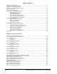
Table of Contents Operator Safety Instructions ............................................................................................................................ 3 Introduction & Machine Specifications ............................................................................................................. 5 Procedures for Transporting Machine ............................................................................................................. 6 Symbols Used on Encore S2426 and L2426 .
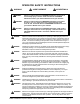
OPERATOR SAFETY INSTRUCTIONS WARNING AVERTISSEMENT ADVERTENCIA DANGER: Failure to read and observe all DANGER statements could result in severe bodily injury or death. Read and observe all DANGER statements found in your Owner's Manual and on your machine. WARNING: Failure to read and observe all WARNING statements could result in injury to you or to other personnel; property damage could occur as well. Read and observe all WARNING statements found in your Owner's Manual and on your machine.
Page WARNING: Maintenance and repairs performed by unauthorized personnel could result in damage or injury. Maintenance and repairs must be performed by authorized Clarke Technology personnel only. WARNING: Any alterations or modifications of this machine could result in damage to the machine or injury to the operator or other bystanders. Alterations or modifications not authorized by the manufacturer voids any and all warranties and liabilities.
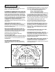
Introduction & Machine Specifications Introduction & Machine Specifications Clarke Technology’s newly designed Encore S2426 and L2426 automatic scrubbers are efficient and superior floor cleaning machines. The Encore uses two brushes to scrub a path 24 or 26 inches wide. A squeegee wipes the floor while the vacuum motor removes the dirty solution from the floor - all in one pass.
Procedures For Transporting How to Put the Machine Into a Van or Truck WARNING: This machine is heavy. Get assistance before attempting to transport or move it. Use two able persons to move the machine on a ramp or incline. Always move slowly. Do not turn the machine on a ramp. Do not stop and leave the machine on a ramp or incline. The loading ramp must be a minimum of 32" wide. WARNING: Machines can topple over if guided over the edges of stairs or loading docks and cause injury or damage.
Procedures For Transpoting (cont.) 11. Fasten the machine to the vehicle. Clarke Technology recommends a strap over the top of the machine and a strap to keep the machine from rolling forward or backwards. If this is not done, there is a possibility of the machine toppling over. Four tie down points (2 along each side of frame) are provided on machine for securing machine. How to Remove the Machine From a Van or Truck 1. Make sure there are no obstructions in the area. 2.
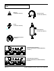
SYMBOLS USED ON ENCORE S2426 and L2426 Warning ("L Class" & "S Class') Solution Control ("L Class" & "S Class") Power ("L Class" & "S Class") Brush Up/Down ("L Class" & "S Class") Traverse Speed Control ("L Class") Traverse Directions Forward (Traverse and Solution, and Brush Rotation) ("L Class" ) Traverse Directions Reverse (Traverse and Solution, and Brush Rotation) ("L Class" ) Page -8- CLARKE TECHNOLOGY Operator's Manual -Encore S2426/L2426
SYMBOLS USED ON ENCORE S2426 and L2426 Solution/Brush Motors ("S Class" ) Warning Label ("L Class" & "S Class") with parking brake Warning Label ("L Class" & "S Class") without parking brake CLARKE TECHNOLOGY Operator's Manual - Encore S2426/L2426 Page -9-
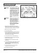
Machine Control Panel Circuit Breakers (See Fig 3, Items "F", "G", "H", "I" & "J") The circuit breaker reset buttons are located on the rear cover. The breakers are located as follows: Item F - Actuator Head (5 amp) Item G - Vacuum Motor (30 amp) Item H& I - Brush Motor (40 amp) Item J - Traverse Motor (25 amp) (L2426 only) If a circuit breaker trips, determine which motor is not operating and turn the key switch "OFF". Wait five minutes and push the reset button back in.
Machine Controls and Features Squeegee Lift Handle, See Figures 4 and 5 The squeegee lift handle is located below the control handles in the center. It is used to raise or lower the squeegee. The vac motor is turned on when the handle is lowered to either the first or last position. Float Shut Off, See Figure 6 The shut-off switch for the vac motor is located in the recovery tank. It automatically turns off the vac motor when the recovery tank is full.
How To Prepare the Machine For Operation How To Install The Batteries The Encore machines uses either two 12-volt batteries or four - 6 volt batteries. The batteries are located in the battery compartment under the recovery tank. To install the batteries, follow this procedure: 1. Turn machine off. Set brake (if equipped). 2. Make sure recovery tank is empty. 3. Tip up the recovery tank until it locks in the full open position. See figure 8A. CAUTION: Before raising the tank, be sure tank is empty.
How To Prepare the Machine For Operation Battery Maintenance The electrical power to operate the machine comes from the storage batteries. Storage batteries need preventative maintenance. WARNING: Working with batteries can be dangerous. Always wear eye protection and protective clothing when working near batteries. NO SMOKING! Correct Level To maintain the batteries in good condition, follow these instructions: 1. Keep the electrolyte at the correct level.
How To Prepare the Machine For Operation How To Charge The Batteries WARNING: Charging the batteries in an area without adequate ventilation could result in an explosion. To prevent an explosion, charge the batteries only in an area with good ventilation. WARNING: Lead acid batteries generate gases which could explode. Keep sparks and flames away from batteries.
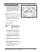
How To Prepare the Machine For Operation 4. Disconnect the battery pack connector from the control housing connector. See figure 14A. 5. Connect the DC connector on the charger to the battery pack connector. See figure 14B. 6. Connect the charger to a properly grounded single phase (3-wire) wall receptacle having the input voltage, frequency, and ampere capacity specified on the nameplate of the charger. For more information on the use of the charger, read the instructions supplied with the charger.
How To Prepare the Machine For Operation How To Remove The Brushes Or Pad Drivers To remove the brushes or pad drivers from the machine, follow this procedure: 1. Turn the key switch "ON". 2. Raise the brush head by pressing and holding the brush switch until brush head is in its full up position. 3. Turn the key switch "OFF" and remove the key. 4. Go to the front of the machine and unlatch front cover. Swing cover open and unlatch the brush housings. 5.
How To Operate The Machine When filling machine from the rear, position clear drain hose against bracket and insert hose as shown in figure 20B Solution level can be viewed from the back of the machine. WARNING: Water solutions or cleaning materials used with this type of machine can leave wet areas on the floor surface. These areas can cause a dangerous condition for the operator or other persons. Always put CAUTION signs near the area you are cleaning.
How To Operate The Machine (cont) How To Clean A Floor WARNING: Water solutions or cleaning materials used with this type of machine can leave wet areas on the floor surfaces. These areas can cause a dangerous condition for the operator or other persons. Always put CAUTION signs near the area you are cleaning. To clean a floor follow this procedure: 1. Set the parking brake (if equipped with machine.) 2. Put the water and a cleaning chemical in the clean solution tank. 3.
Maintenance WARNING: Maintenance and repairs must be done by authorized personnel only. WARNING: Always empty the solution tank and recovery tank before doing any maintenance. WARNING: Keep all fasteners tight. These Maintenance Procedures Must Be Done Every Day Keep the machine clean, it will need fewer repairs and have longer life. Figure 22 Do These Procedures When You Begin Your Work Period 1. Turn off key switch. A 2. Disconnect AC power from battery charger (follow charger instructions). 2.
Maintenance Do These Procedures When You End Your Work 1. Drain the solution tank (Figure 25) and the recovery tank (Figure 26). To drain the tanks , follow this procedure: a. Turn the key switch “OFF”. b. Remove the drain hose from the back of the machine. c. Put the end of the hose over a drain or bucket. Figure 25 d. Recovery Tank: 1.) Turn the valve handle to the left. Pull the handle out to open the drain (Figure 27).
Maintenance Maintenance Procedures To Be Done Every Week: WARNING: Maintenance and repairs must be done by authorized personnel only. Always empty the solution tank and the recovery tank before doing any maintenance. Keep all fasteners tight. WARNING: Always wear eye protection and protective clothing when working near batteries. Do not put tools or other metal objects across the battery terminals or the tops of the batteries.
Maintenance Maintenance For The Squeegee To remove the squeegee, follow this procedure: 1. Remove the squeegee assembly by loosening the two knobs that attach the squeegee to the machine. Pull the squeegee assembly off. See figure 31. 2. Inspect the squeegee blade. 3. If the blade is worn, turn the blade so that a new edge is in the wiping position. Figure 31 4. Reinstall squeegee assembly on the machine.
Maintenance cont. A Consult your Clarke Technology Authorized Service Person to do the service procedures. Use only genuine Clarke Technology parts. How to Clean the Solution Line If the solution line becomes clogged follow this procedure: B 1. Turn key switch "OFF" and remove the key. 2. Open brush motor cover and remove brush housing. Figure 34 3. Remove brushes / pads. 4. Locate the solution valve. It is located behind the brush motor. 5. Turn solution valve "OFF". See figure 34, A) 6.
Maintenance cont. 3. Turn the key switch "OFF" and remove the key. 4. Tip up the recovery tank until it locks in the full open position. 5. Go to the front of the machine and unlatch the front cover and swing cover open. 6. Locate the four mounting studs on the brush head bracket. See figure 35. The top two mounting nuts can be accessed through the top of the solution tank. The lower two can be accessed through the front. Loosen the four mounting nuts 2 to 3 turns counterclockwise.
Clarke Technology Encore S2426 and L2426 Accessories - 5/01 ACCESSORIES Description Power Wand System Kit Clarke Care Kit 39" Squeegee Assembly 32" Squeege Assembly Poly Dur Protectant Kit, Grease Gun Kit, Low Voltage Shut-Off Brake Kit Assembly "L" Brake Kit Assembly "S" Accessory Bag Hour Meter Kit Soft Caster Assembly Gimbal, Brush "L" Gimbal, Brush Spring "L" Dual Direct Clutch Plate "S" Spacer for 30034A Clutch Plate "S" Center Lock Pad Retainer Kit, Solution Fill Brushes and Pad Assemblies: Size Des
NOTES Page -26- CLARKE TECHNOLOGY Operator's Manual -Encore S2426/L2426
ENCORE S2426 and L2426 Section II Parts and Service Manual (70200A) CLARKE TECHNOLOGY Operator's Manual - Encore S2426/L2426 Page -27-
HOW TO CORRECT PROBLEMS IN THE MACHINE PROBLEM There is no solution flow. The solution flow does not stop. The machine does not remove all the water from the floor. The batteries do not give the normal running time. Page -28- CAUSE ACTION The solution tank is empty. Fill the solution tank. The solution valve is closed. Open the solution valve. There is an obstruction in the solution hose or filter. Remove the obstruction from the hose or filter.
PROBLEM The cleaning is not even. CAUSE ACTION The scrub brush or pad is worn. Replace the scrub brush or pad. There is damage to the brush assembly, caster or the solution valve. Have an authorized service person make the needed repairs. The brush motor is not running Check for tripped breaker. Reset. Check for loose connections. The solution level is low. Fill the solution tank. NOTE: If the problem continues consult an authorized service person. The machine does not run.
CLARKE TECHNOLOGY Encore S2426/ L2426 Final Assembly Drawing 11/23/00 1 4 2 3 5 6 27 31 28 30 26 27 32 7 29 25 15 9 8 24 4 10 11 8 23 22 20 19 9 21 17 8 10 11 8 12 18 13 14 16 8 10 11 Page -30- CLARKE TECHNOLOGY Operator's Manual -Encore S2426/L2426
CLARKE TECHNOLOGY Encore S2426/L2426 Final Assembly Parts List 11/23/00 Ref. # 1 2 Part No.
CLARKE TECHNOLOGY Encore S2426/L2426 Recovery Tank Assembly Drawing 8/00 Drawing #10062A 1 2 43 3 4 5 42 41 6 8A 43 7 40 8B 9 8 10 39 37 38 36 35 20 19 7 34 12 18 17 16 26 18 27 30 16 14 28 33 13 11 15 31 25 32 24 23 29 21 22 #40 Recommended Torque 175 + or - 5 inch pounds Page -32- CLARKE TECHNOLOGY Operator's Manual -Encore S2426/L2426
CLARKE TECHNOLOGY Encore S2426/L2426 Recovery Tank Assembly Parts List 8/00 Ref. # 1 2 3 4 5 6 7 8 8A 8B 9 10 11 12 13 14 15 16 17 18 19 20 21 22 23 24 25 26 27 28 29 30 31 32 33 34 35 36 37 38 39 40 41 42 43 NI NI Part No.
CLARKE TECHNOLOGY Encore S2426/L2426 Solution Tank Assembly Drawing 5/01 Drawing #10063A 19 20 21 25 23 18 2 1 24 3 17 16 5 22 12 9 4 5 6 10 5 11 7 5 8 5 13 8 14 Page -34- 5 5 CLARKE TECHNOLOGY Operator's Manual -Encore S2426/L2426
CLARKE TECHNOLOGY Encore S2426/L2426 Solution Tank Assembly Parts List 5/01 Ref. # 1 2 3 4 5 6 7 8 9 10 11 12 13 14 15 16 17 18 19 20 21 22 23 24 25 NI NI Part No.
CLARKE TECHNOLOGY Encore S2426/L2426 Rear Panel Assembly Drawing 8/00 Drawing #10064A (L) Drawing #10067A (S) 1 2 1 2 36 5 4 3 34 35 6 7 34 32 33 8 9 9 10 31 10 9 10 6 29 28 3 11 27 3 10 30 11 15 16 17 16 15 37 26 25 24 18 14 21 23 Page 2 22 -36- 20 19 13 12 CLARKE TECHNOLOGY Operator's Manual -Encore S2426/L2426
CLARKE TECHNOLOGY Encore S2426/L2426 Rear Panel Assembly Parts List 5/01 Ref. # Part No.
CLARKE TECHNOLOGY Encore S2426/L2426 Control Panel Assembly Drawing 8/00 Drawing #10065A "L" and 10066A "S" 1 2 4 7 37 3 5 34 6 35 36 27 38 36 28 29 11 12 8 7 11 10 14 30 40 32 31 33 19 27 18 1516 15 16 30 26 16 25 39 16 15 17 15 2 5 5 24 23 20 22 9 21 Page -38- CLARKE TECHNOLOGY Operator's Manual -Encore S2426/L2426 3
CLARKE TECHNOLOGY Encore S2426/L2426 Control Panel Assembly Parts List 8/00 Ref. # 1 2 3 4 5 6 7 8 9 10 11 12 13 14 15 16 17 18 19 20 21 22 23 24 25 26 27 28 29 30 31 32 33 34 35 36 37 38 39 40 NI NI NI Part No.
CLARKE TECHNOLOGY Encore S2426/L2426 Squeegee Lift Assembly Drawing 6/00 Drawing # 10075A 15 1 20 21 19 6 12 2 22 3 4 17 5 6 15 15 16 8 8 9 7 10 14 13 11 18 Page -40- CLARKE TECHNOLOGY Operator's Manual -Encore S2426/L2426
CLARKE TECHNOLOGY Encore S2426/L2426 Squeegee Lift Assembly Parts List 6/00 Ref. # 1 2 3 4 5 6 7 8 9 10 11 12 13 14 15 16 17 18 19 20 21 22 Part No.
CLARKE TECHNOLOGY Encore S2426/L2426 Squeegee Assembly Drawing 10/00 Drawing # 10068A and 10129A 1 6 2 19 3 4 4 5 18 20 7 17 8 9 10 11 12 13 14 16 15 Page -42- CLARKE TECHNOLOGY Operator's Manual -Encore S2426/L2426
10 11 12 13 14 15 16 17 18 19 20 Part No. 962720 980657 60243A 30049B 81104A 60254A 50958A 30048A 60272A 60234A 50835A 930086 60252A 60232A 30069A 30067A 30058A 30047A 30091A 30066A 80011A 81301A 34260B 25201A 60358A Description Screw, ¼-20 x ½ Hex SS Washer, ¼ Lock Bracket, Squeegee Wheel Wheel, Squeegee Nut, ¼-20 Bolt, Shoulder 5/16x 2¼ Ring, 3/8 ID Snap Wheel, Guide, 4 Inch Diameter Channel, Squeegee Weldment 39” Channel, Squeegee Weldment 32” Latch, Squeegee Clamp Rivet, 3/16 x .
CLARKE TECHNOLOGY Encore S2426/L2426 Frame Axle Assembly Drawing 11/23/00 Drawing #10069A and 10070A 22 20 Page -44- CLARKE TECHNOLOGY Operator's Manual -Encore S2426/L2426
Tr av er se No nTr av er se CLARKE TECHNOLOGY Encore S2426/L2426 Frame Axle Assembly Parts List 11/23/00 Ref. # 1 2 3 4 5 6 7 8 9 10 11 12 13 14 15 16 17 18 19 20 21 22 23 24 25 26 27 28 29 30 31 32 Part No.
CLARKE TECHNOLOGY Encore S2426/L2426 Brush Head Assembly Drawing 8/00 Drawing #10071A and 10061A 1 2 1 3 45 67 77 8 9 72 10 71 6 68 70 60 21 76 69 75 64 63 59 62 74 25 67 58 11 73 7 12 13 15 66 65 16 14 17 61 11 57 55 20 56 54 15 18 19 22 21 53 23 52 31 30 51 24 29 50 25 49 28 52 25 48 46 45 44 42 47 39 38 32 37 41 40 26 33 31 43 41 40 27 34 38 37 36 35 Page -46- CLARKE TECHNOLOGY Operator's Manual -Encore S2426/L2426
CLARKE TECHNOLOGY Encore S2426/L2426 Brush Head Assembly Parts List 8/00 Drawing #10071A and #10061A Ref. # 1 2 3 4 5 6 7 8 9 10 11 12 13 14 15 16 17 18 19 20 21 22 23 24 25 26 27 28 29 30 31 32 33 34 35 36 37 38 39 Part No.
CLARKE TECHNOLOGY Encore S2426/L2426 Optional Brake Drawing and Parts List 11/23/00 10073A - "S" Model 1 11 7 4 14 5 2 5 3 1 2 4 15 7 4 11 5 12 13 16 15 6 4 15 6 6 8 11 9 10 5 7 14 5 5 4 12 11 5 4 54 Ref. # 1 2 3 4 5 6 7 8 9 10 11 12 13 14 15 16 NI Page -48- Part No. 85811A 60359A 60271A 920110 980651 67877A 85814A 60268A 60361A 60267A 81104A 848508 87026A 50969A 87607A 60362A 77266B Description Screw, 5/16-18 x ¾ Pad, Brake Brake, Bar L.H.
CLARKE TECHNOLOGY Encore S2426/L2426 Optional Brake Drawing and Parts List 5/01 10072A - "L" Model 3 4 5 6 2 1 7 8 Ref # 1 2 3 4 5 6 7 8 Part No. 50981A 60388A 30095A 80123A 80125A 30094A 80124A 10160A Description Spacer Tie, Cover Retainer Nut, Brake Drive Key, 3/32 Sq. x 1/4 Lg. Cover, Vinyl Screw Set (Brake Nut to Motor Shaft) Brake, Asm. 24V Qty 1 1 1 1 1 2 1 NOTE: Only use spacer (ref. #2) on transaxles that have a circular step and mounting nuts protruding from end of motor.
CLARKE TECHNOLOGY Encore S2426/L2426 Vacuum Motor Drawing and Parts List Drawing 5/00 TO Page -50- CLARKE TECHNOLOGY Operator's Manual -Encore S2426/L2426
CLARKE TECHNOLOGY Encore S2426/L2426 Gearbox Assembly Drawing and Parts List 5/00 Form #54238A 9 8 7 6 4 5 3 2 1 Ref # 1 2 3 4 5 6 7 8 9 10 Part No. 57846A 507641 52050A 56668A 51176a 58316A 902605 54883A 58144A NI Description Ring, Snap Seal, Oil, Small Cap End O-Ring Bearing, Large Shaft & Gear Bearing, Small Housing Seal, Oil Large Darina EP2 Grease CLARKE TECHNOLOGY Operator's Manual - Encore S2426/L2426 Qty 1 1 1 1 1 1 1 1 1 4 oz.
CLARKE TECHNOLOGY Encore S2426/L2426 Brush Motor Drawing & Parts List 8/00 Motor Asm. 44809B 13 7 12 1 12 2 Seam Location 13 3 14 4 15 5 6 16 17 8 9 10 11 Item 1 2 3 4 *5 Part No. 56478A 50142A 902654 902550 6 7 8 9 10 11 12 13 * 14 15 16 17 50520A 56480A 962546 50517A 448396 40826A 55657A 55656A 50515A 80501A 54238A Description Qty Stator Frame Assembly (w/Magnets & Clips) 1 Armature Assembly (w. B.E. & F.E. Bearings) 1 Bearings B.E. 1 Bearing F.E.
CLARKE TECHNOLOGY Encore S2426/L2426 Transaxle Drawing 5/00 CLARKE TECHNOLOGY Operator's Manual - Encore S2426/L2426 Page -53-
CLARKE TECHNOLOGY Encore S2426/L2426 Battery Charger Drawing and Parts List 5/00 WARNING: All electrical repairs must be performed by qualified personnel only. Charger #40512A: 24 volt, 25 amp D.C., 115 volt, A.C., 60 Hz. Charger #40513A: 24 volt, 25 amp D.C., 230 volt, A.C., 50 Hz Ref. No. 1 2 3 4 5 6 7 8 9 10 11 12 13 Description Charger Case Transformer Electronic Controller Kit Capacitor, 660 V.A.C. Heat Sink Assembly Ammeter Fuse Holder Strain Relief, A.C. Cord Strain Relief, D.C. Cord D.C.
CLARKE TECHNOLOGY Encore S2426 Connection Diagram (00932A-W) 6/00 CLARKE TECHNOLOGY Operator's Manual - Encore S2426/L2426 Page -55-
CLARKE TECHNOLOGY Encore S2426 Electrical Schematic (00932A-E) 5/00 Page -56- CLARKE TECHNOLOGY Operator's Manual -Encore S2426/L2426
CLARKE TECHNOLOGY Encore L2426 Connection Diagram (00950A - W) 6/00 CLARKE TECHNOLOGY Operator's Manual - Encore S2426/L2426 Page -57-
CLARKE TECHNOLOGY Encore L2426 Electrical Schematic (00950A-E) 5/01 Page -58- CLARKE TECHNOLOGY Operator's Manual -Encore S2426/L2426
ALTO® PRODUCT SUPPORT BRANCHES U. S. A. Locations HEAD OFFICE European Locations PRODUCTION FACILITIES ALTO U.S. Inc., St. Louis, Missouri 16253 Swingley Ridge Road, Suite 200 Chesterfield, Missouri 63017-1725 PRODUCTION FACILITIES ALTO U.S. Inc., Springdale, Arkansas 2100 Highway 265 Springdale, Arkansas 72764 (501) 750-1000 Customer Service - 1-800-253-0367 Technical Service - 1-800-356-7274 ALTO U.S. Inc., Bowling Green, Ohio 43402 1100 Haskins ALTO U.S. Inc., Clearwater, Florida 33765 1500 N.
CLARKE TECHNOLOGY LIMITED U.S. WARRANTY This Clarke Technology Industrial/Commercial Product is warranted to be free from defects in materials and workmanship under normal use and service for a period of three years from the date of purchase, when operated and maintained in accordance with Clarke Technology's Maintenance and Operations instructions. Motors must be inspected for carbon motor brush wear at six-month intervals by an authorized Clarke Technology repair station.