www.clarke-tech.
Flat-200 Twin HD-Ready Inhaltsangabe Inhaltsangabe ............................................ Sicherheitsanweisungen .............................. Beschreibung der Antenne ........................... Tabelleninhalt ............................................. Wo wird die Antenne angebracht? ................ Anbringen der Antenne ............................... 1) Grundsätzliche Montage ....................... 2) Montageset für den Balkon .................. 3) Montageset für die Außenwand ............
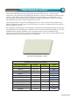
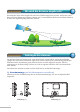
Flat-200 Twin HD-Ready Beschreibung der Antenne Flat-200 Twin HD-Ready ist eine doppelt polarisierte Satellitenantenne – senkrecht und waagerecht - die speziell für den Empfang der meisten, in Europa verwendeten Satelliten ausgerichtet ist. NEO-VH200 ermöglicht den Empfang des Gesamtangebots von CANALSAT in zwei Ausrichtungen. Aufgrund der Dualität des Universal LNB (zwei Ausgaben) können zwei SettopBoxen gleichzeitig an die Antenne angeschlossen werden.
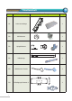
Flat-200 Twin HD-Ready Tabelleninhalt Symbol Teilebe-zeichnung A1 Antennenmontage 1 B0 LNB-Klammer 1 B0 Spiegelklammer 1 B2 Haltestange 1 B3 Stützklammer Fenster 1 B4 Befestigungs-klammer A 1 4 Darstell-ung Menge
Symbol B5 B6 Teilebe-zeichnung Befestigungs-klammer B Gleitträger Fenster Darstell-ung Menge 1 1 B7 Spannstück 1 M1 Sechskant-BolzenM4x10 SEMS2 5 M2 Sechskant-BolzenM6x20 SEMS2 1 M3 Sechskant-BolzenM6x45 SEMS2 1 M4 T.D.0-Bolzen M6x45 5 M5 T.D.
Wo wird die Antenne angebracht? Flat-200 Twin HD-Ready Ihre Antenne muss außen angebracht und nach SÜDEN ausgerichtet werden. Stellen Sie sicher, dass sich keine Hindernisse (Häuser, Bäume usw.) in unmittelbarer Nähe des Satelliten befinden, da diese den Signalempfang behindern können. Anbringen der Antenne Flat-200 Twin HD-Ready Die Antenne kann auf einem Dach, einer Fensterbank, einem Balkon, einem freistehenden Trääger oder auf einem Gartentisch angebracht werden.
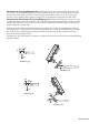
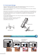
Montieren Sie die Spiegelklammer (B1): Befestigen Sie B1 mit den Schrauben (M2) und (M3) Anbringen Antenne wie in Abb. (3) an der Haltestangeder (B2). Verwenden Sie die Feder- und Unterlegscheiben für M2 und M3 sowie das Spannstück (B7) zum Anziehen. M2 und M3 sollten nicht zu fest gezogen werden, da der Azimutwinkel später eventuell für die Signalsuche eingestellt werden muss.
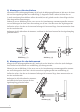
2) Montageset für den Balkon Montieren Sie die Befestigungsklammer B (B5) und die Befestigungsklammer A (B4) mit 4 der Sorte M5 und den zugehörigen M6 wie in Abbildung (7) dargestellt. Mit B7 ziehen Sie diese fest an. Je nach Ausrichtung Ihres Balkons sollten B4 und B5 um 90° gedreht werden, dann folgen Sie den oben dargestellten Anweisungen.
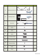
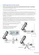
4) Montageset für die Fensterbank Montieren Sie den Fenstergleitträger (B6) und die Befestigungsklammer B (B5) wie in Abbildung (10-1) mit den Schrauben (M1). Dazu benötigen Sie einen Kreuzschraubenzieher. Die Schrauben sollten nicht zu fest angezogen werden. Führen Sie wie in Abbildung (10-2) die zuvor montierte Antenne in B5 ein und befestigen Sie diese mit 2 der M4 sowie den zugehörigen M6.
5) Freistehende Montage Legen Sie die Befestigungsklammer A (B4) mit der flachen Seite nach oben wie in Abb. (13) angegeben. Befestigen Sie die 4 Gummis (E 1) von der Unterseite. Legen Sie die Spiegelklammer (B1) in die Mitte der Befestigungsklammer A (B4) und schrauben Sie diese (M2) mit B7 fest. Montieren Sie die Antenne (A1) wie in Abb. (14), indem Sie die Rückseite in die Spiegelklammer (B1) schieben. Befestigen Sie A1 mit Schrauben (M4) und aufgerauten Muttern (M6).
Flat-200 Twin HD-Ready Ausrichtung der Antenne Stellen Sie sicher, dass die Antenne horizontal ausgerichtet ist. Ändern Sie den Erhebungswinkel der Antenne entsprechend Ihrem Wohnort (siehe Azimut-, Erhebung- & LNB-Tabelle auf Seite 13-15) und richten Sie die Antenne nach Süden aus. (Der Erhebungswinkel ist auf der Spiegelklammer eingraviert.
2) Einstellung des Erhebungswinkel Stellen Sie den Erhebungswinkel ein, dass er am Satellitenempfang ausgerichtet ist. Befestigen Sie ihn mit einer Schraube an B1. B1 3) LNB-Einstellungen Für die meisten Montagestandorte sind die Azimut- und Erhebungseinstellungen ausreichend, für ein besseres Empfangssignal sind LNB-Feineinstellungen unerlässlich. Eine LNB-Einstellung erfolgt durch eine Feineinstellungsklammer. Diese Winkelangabe befindet sich auf der Antennenhalterung.
Flat-200 Twin HD-Ready Tabellen der Theoretischen Werte Eventuell sind minimale Feineinstellungen notwendig. Dazu verbinden Sie die Satellitenantenne mit Ihrem Decoder und schlagen im Handbuch der Satellitenanlage die Seite “AUSRICHTUNG ANTENNE” auf. Hinweis: Durch genaue Feineinstellungen erhalten Sie einen optimalen Empfang (sogar bei schlechtem Wetter), Fachleute benutzen dazu ein “Signalmeter”. Es zeigt sehr genau an, welche Frequenzen die Anlage empfängt.
www.clarke-tech.
Flat-200 Twin HD-Ready Contents Contents .............................................. 2 Safety Instructions ................................. 2 Antenna Description .............................. 3 Contents of the Box ............................... 4 Where to Install Your Antenna ? .............. 6 Installation of the Antenna ...................... 6 1) Basic Assembly .............................. 6 2) Balcony Mount Assembly ................ 8 3) Wall Mount Assembly ......................
Flat-200 Twin HD-Ready Antenna Description Flat-200 Twin HD-Ready is a dual polarized satellite antenna – vertical and horizontal – especially suited for the reception of most satellites used in Europe. Flat-200 Twin HD-Ready allows the reception of the totality of CANALSAT le bouquet in both polarization. Because of the duality of the universal LNB (two outputs), you can connect two settop boxes to the antenna simultaneously.
Flat-200 Twin HD-Ready Symbol Contents of the Box Part Name Image Quantity A1 Antenna Ass’y 1 B0 Skew Bracket 1 B1 Body Bracket 1 B2 Support Bar 1 B3 Window Support Bracket 1 B4 Joint Bracket A 1 4
Symbol Part Name Image Quantity B5 Joint Bracket B 1 B6 Window Slide Bracket 1 B7 Spanner 1 M1 Hex Bolt M4×10 SEMS2 6 M2 Hex Bolt M6×20 SEMS2 1 M3 Hex Bolt M6×45 SEMS2 1 M4 T.D.C Bolt M6×45 5 M5 T.D.
Where to Install Your Antenna? Flat-200 Twin HD-Ready Your antenna must be installed outside oriented toward SOUTH. Make sure that there are no obstacles (buildings, trees, etc.) in the direction of the satellite for obstacles may block the satellite signal. Installation of the Antenna Flat-200 Twin HD-Ready The antenna can be installed on a roof, on the windowsill, in balcony, on a free-standing pole, or on an outdoor table.
Assemble the Body Bracket (B1): Attach B1 to the Support Bar (B2) with the screws (M2) & (M3) as in Figure (3). Be sure to use spring & flat washers for M2 and M3, using the Spanner (B7) for tightening. Do not tighten M2 & M3 too hard, because you may later need to calibrate the azimuth angle for the signal search. Assemble the Antenna Ass'y (A1) as in Figure (4): Slide the back of A1 into B1 . Fixate A1 withthe screws (M4) & the scratched nuts (M6).
2) Balcony Mount Assembly Assemble the Joint Bracket B (B5) and the Joint Bracket A(B4) with 4 of M5s & the accompanying M6s as in Figure(7). Use B7 to tighten securely. Depending on the balcony structure, you may turn 90° of B4 & B5 and follow the instruction above. As in Figure(8), insert the whole antenna set previously assembled as in Basic Type Assembly above, and tighten it with 2 of M4s and the accompanying of M6s using B7.
3) Wall Mount Assembly Attach the Joint Bracket (B5) perpendicularly to the wall with ankles & screws (not provided) as in Figure (9). Insert the whole antenna set previously assembled as in Basic Type Assembly above and tighten it with 2 of M4s and the accompanying M6s as in Figure (9). Make sure that B2 attached to the antenna is horizontally placed and mount it with all the remaining M6s. Tighten firmly all the screws of the antenna once you find a final position for the best signal quality.
M1 B5 B6 Figure (10-1) A1 M1 M6 Figure (10-2) A1 M4 Figure (11) A1 M6 B2 M1 B3 M4 Figure (12) 10
5) Stand-alone Assembly Place the Joint Bracket A (B4) with its flat surface up as in figure (13). Fix the 4 rubbers (E1) from the bottom. Place the Body Bracket (B1) in the center of the Joint Bracket A (B4) and fixate it with screws (M2) using B7. Assemble the antenna (A1) as in Figure (14) by slipping the back of it into the Body Bracket (B1). Fix A1 with screws (M4) & scratched nuts (M6).
Flat-200 Twin HD-Ready Orientation of the Antenna Ensure that the antenna be horizontally placed. Change the elevation angle of the antenna according to your location (check azimuth, elevation & skew table on page 14~19) then change the orientation of the antenna approximately near the due south. (Elevation angle is engraved on the body bracket.) Seeing the signal level shown on of your settop box, you can adjust the azimuth angle to the maximum reception point.
2) Azimuth Calibration The orientation angle of your antenna depends on the satellite which you wish to receive. Search with a compass. The due South is at 180°. NORTH WEST EAST SOUTH To receive ASTRA satellite turn the compass until the coloured part of the needle (black or red in general) coincide with the north (0°). Maintain the compass in this direction, seeking the value of the azimuth selected. It indicates the direction of the satellite.
Tables of the Theoretical Values Flat-200 Twin HD-Ready France 13.0 E 19.
Flat-200 Twin HD-Ready Great Britain 13.0˚ E 19.
Flat-200 Twin HD-Ready City 13.0˚ E 19.2˚ E HOT BIRD ASTRA 1F/G/H/KR/L 6/7A/8 City 13.0˚ E 19.
Flat-200 Twin HD-Ready City 19.2˚ E 13.0˚ E ASTRA HOT BIRD 1F/G/H/KR/L 6/7A/8 City 19.2˚ E 13.
Flat-200 Twin HD-Ready City 13.0˚ E 19.2˚ E HOT BIRD ASTRA 1F/G/H/KR/L 6/7A/8 City 13.0˚ E 19.
Flat-200 Twin HD-Ready City 13.0˚ E 19.2˚ E HOT BIRD ASTRA 1F/G/H/KR/L 6/7A/8 City 13.0˚ E 19.2˚ E HOT BIRD ASTRA 1F/G/H/KR/L 6/7A/8 City 13.0˚ E 19.2˚ E HOT BIRD ASTRA 1F/G/H/KR/L 6/7A/8 City 13.0˚ E 19.2˚ E HOT BIRD ASTRA 1F/G/H/KR/L 6/7A/8 Austria Wien Landeck Az El Sk Az El Sk 176.0 34.6 -2.5 168.3 35.2 -7.9 184.5 34.6 3.0 167.7 35.8 -2.2 Linz Graz Az El Sk Az El Sk 173.5 34.3 -4.4 174.8 35.8 -3.5 181.7 34.5 1.2 183.3 35.8 2.3 (Unit: deg.