
User's Manual
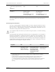
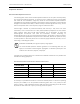
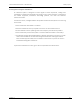
Table Of Contents
- About This Manual
- About the Clarius Ultrasound Scanner
- Using the Clarius Ultrasound Scanner
- Accessories
- Cleaning & Disinfecting
- Safety
- References
- Measurement Accuracy Tables
- Acoustic Output Tables
- Clarius Scanner C3 HD3: B-Mode
- Clarius Scanner C3 HD3: Color Doppler Mode
- Clarius Scanner C3 HD3: M-Mode
- Clarius Scanner C3 HD3: PW Doppler Mode
- Clarius Scanner C7 HD3: B-Mode
- Clarius Scanner C7 HD3: Color Doppler Mode
- Clarius Scanner C7 HD3: M-Mode
- Clarius Scanner C7 HD3: PW Doppler Mode
- Clarius Scanner EC7 HD3: B-Mode
- Clarius Scanner EC7 HD3: Color Doppler Mode
- Clarius Scanner EC7 HD3: M-Mode
- Clarius Scanner EC7 HD3: PW Doppler Mode
- Clarius Scanner L7 HD3: B-Mode
- Clarius Scanner L7 HD3: Color Doppler Mode
- Clarius Scanner L7 HD3: M-Mode
- Clarius Scanner L7 HD3: Needle Enhance B-Mode
- Clarius Scanner L7 HD3: Ocular (Ophthalmic) B-Mode
- Clarius Scanner L7 HD3: PW Doppler Mode
- Clarius Scanner L15 HD3: B-Mode
- Clarius Scanner L15 HD3: Color Doppler Mode
- Clarius Scanner L15 HD3: M-Mode
- Clarius Scanner L15 HD3: Needle Enhance B-Mode
- Clarius Scanner L15 HD3: Ocular (Ophthalmic) B-Mode
- Clarius Scanner L15 HD3: PW Doppler Mode
- Clarius Scanner L20 HD3: B-Mode
- Clarius Scanner L20 HD3: Color Doppler Mode
- Clarius Scanner L20 HD3: Ocular (Ophthalmic) B-Mode
- Clarius Scanner L20 HD3: M-Mode
- Clarius Scanner L20 HD3: Needle Enhance B-Mode
- Clarius Scanner L20 HD3: PW Doppler Mode
- Clarius Scanner PA HD3: B-Mode
- Clarius Scanner PA HD3: Color Doppler Mode
- Clarius Scanner PA HD3: M-Mode
- Clarius Scanner PA HD3: PW Doppler Mode
- Clarius Scanner PA HD3: Transcranial B-Mode
- Clarius Scanner PA HD3: Transcranial Color Doppler Mode
- Clarius Scanner PA HD3: Transcranial M-Mode
- Clarius Scanner PA HD3: Transcranial PW Doppler Mode
- Revision History

Clarius Ultrasound Scanner - HD3 Scanners Safety Topics
revision 1 60
*For ETSI 301 489-1 and ETSI 301 489-17: Tested in transmit mode only, no idle mode exists for
this product.
Electromagnetic Interference
The way an electromagnetic interference (EMI) from other equipment affects the Clarius
Ultrasound Scanner depends on the system's operation mode, image control settings, and the
type and level of electromagnetic phenomena. Electromagnetic phenomena may be
intermittent, making it difficult to identify the source.
If you experience EMI, use caution if you continue using the system, or consider relocating
your system.
The following table describes typical interferences seen in imaging systems. It is impossible to
describe all manifestations of interference because it depends on many parameters of the
transmitting equipment, for example, the type of modulation used by the signal carrier, the
source type, and the transmitted level. It is also possible for the interference to degrade the
imaging system's performance and become invisible on the image. If the diagnostic results are
suspicious, confirm the diagnosis using other methods.
Power frequency magnetic field immunity
test
IEC 61000-4-8
30A/M 30A/M
Voltage dips/ interruptions
IEC 61000-4-11
0% for 0.5 cycle @ 0º, 45º, 90º, 135º,
180º, 225º, 270º, 315º
0% for 1 cycle @ 0º
70% for 25/30 cycles (50/60 Hz) @ 0º
0% for 250/300 cycles @ 0º
0% for 0.5 cycle @ 0º, 45º, 90º, 135º,
180º, 225º, 270º, 315º
0% for 1 cycle @ 0º
70% for 25/30 cycles (50/60 Hz) @ 0º
0% for 250/300 cycles @ 0º
Imaging Mode
ESD
a
a. Electrostatic discharge caused by discharging of electric charge buildup on insulated
surfaces or persons.
RF
b
b. Radio frequency energy from RF transmitting equipment such as portable phones,
hand-held radios, wireless devices, commercial radio and TV stations, and so on.
Power Line
c
c. Conducted interference on power lines or connected cables caused by other equipment,
such as switching power supplies, electrical controls, and natural phenomena such as
lightning.
B-Mode Change of operating mode,
system settings, or system
reset. Brief flashes in the
displayed or recorded image.
For sector imaging scanners,
white radial bands or flashes in
the center lines of the image.
For linear imaging scanners,
white vertical bands, sometimes
more pronounced on the sides
of the image.
White dots, dashes, or
diagonal lines near the
center of the image.