Model K20 installation guide ProSecurity NOTE: This product is intended for installation by a professional installer only! Any attempt to install this product by any person other than a trained professional may result in severe damage to a vehicle’s electrical system and components.
table of contents Primary Harness (H1), 18-pin connector . . . . . . . . . . . . . . . . . . . . . . . . . . . . . . . . . . . . . . . . . . . . . . . . . . . . . . 4 Peripheral Plug-In Harnesses . . . . . . . . . . . . . . . . . . . . . . . . . . . . . . . . . . . . . . . . . . . . . . . . . . . . . . . . . . . . . . 7 Super Bright LED, 2-Pin WHITE Plug . . . . . . . . . . . . . . . . . . . . . . . . . . . . . . . . . . . . . . . . . . . . . . . . . . . . . . . . 7 Valet/Program Switch, 2-Pin BLUE Plug . .
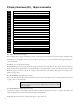
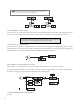
Primary Harness (H1), 18-pin connector H1/1 ___ RED H1/2 ___ BLUE H1/3 ___ BLACK/WHITE-1 H1/4 ___ BLACK/WHITE H1/5 ___ GREEN/BLACK H1/6 ___ WHITE/BLACK H1/7 ___ VIOLET/BLACK H1/8 ___ BLUE/BLACK H1/9 ___ VIOLET H1/10 ___ WHITE (+/-) PARKING LIGHT FLASH OUTPUT H1/11 ___ BLACK (-) CHASSIS GROUND INPUT H1/12 ___ BROWN H1/13 ___ LT.
H1/5 GREEN/BLACK Lock #30 Common (Output) The system has door lock relays on-board, and can directly interface with most electric power door lock systems drawing 30 amps or less. It can also drive aftermarket actuators directly. (Some vehicles require that an aftermarket actuator be added to the driver’s door to allow system control, see Type D wiring section in Tech Tip Document 1041). H1/6 WHITE/BLACK Lock #87 Normally Closed See H1/5. H1/7 VIOLET/BLACK Lock #87 Normally Opened (Input) See H1/5.
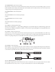
note: In most instances the negative pulse output can be connected directly to the factory disarm wire. The circuit shown on the left below is provided for those instances where direct connection will not correctly function. H1/14 WHITE/BLUE (-) Channel 3 Output This wire provides a (-) 200 mA output whenever the transmitter code controlling Channel 3 is received. This output will continue as long as that transmission is received.
H1/18 RED/WHITE Channel 2, 200mA (-) output When the system receives the transmitter code controlling Channel 2 for longer than 1.5 seconds, the red/white wire will supply an output as long as the transmission continues. This is often used to operate a trunk/hatch release or other relay-driven functions. IMPORTANT! Never use this wire to drive anything but a relay or a low-current input! The transistorized output can only supply 200 mA of current.
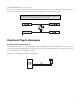
Valet/Program Switch, 2-Pin BLUE Plug The Valet/Program button should be accessible from the driver’s seat. It plugs into the BLUE port on the side of the unit. Consider how the button will be used before choosing a mounting location. Check for rear clearance before drilling a 9/32-inch hole and mounting the button. System Features Learn Routine The System Features Learn Routine dictates how the unit operates. It is possible to access and change any of the feature settings using the Valet®/Program switch.
The learn routine will be exited if: ➤ The ignition is turned on. ➤ The Valet/Program switch is pressed too many times. ➤ More than 15 seconds elapses between programming steps. One long horn honk (if connected) indicates that the Learn Routine has been exited.
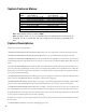
System Features Menus Feature Number Default LED ON Setting (Press Channel 1) LED OFF Setting (Press Channel 2) 1 Ignition-controlled door lock ON Ignition-controlled door lock OFF 2 Ignition-controlled door unlock ON Ignition-controlled door unlock OFF 3 Ignition-controlled domelight ON Ignition-controlled domelight OFF 4 0.8 second door lock pulses 3.5 second door lock pulses/0.4 sec.
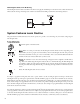
Transmitter/Receiver Learn Routine The system comes with two transmitters that have been taught to the receiver. The receiver can store up to four different transmitter codes in memory. Use the following learn routine to add transmitters to the system or to change button assignments if desired. 1. Key. Turn the key to the ON position. 2. Choose. Within 10 seconds, press and release the Valet/program switch the number of times corresponding to the desired channel listed below.
Transmitter Configurations The transmitters can be programmed with the standard or single button arm/disarm configurations by using the Auto Learn functions in the Transmitter/Receiver Learn Routine. Standard Configuration A remote that uses the standard configuration operates similarly to many factory keyless entry remotes. A standard configuration transmitter allows arming, disarming, and Panic Mode activation with separate buttons.
LIGHT FLASH JUMPER Valet Switch LED VIOLET Unlock #87 Normally Open (Input) RED/WHITE (-) Output of Channel 2 BLUE/BLACK Unlock #30 Common Output BROWN/BLACK Unlock #87A Normally Closed VIOLET/BLACK Lock #87 Normally Open (Input) ORANGE (-) 500 mA Ground-When-Armed Output WHITE/BLACK Lock #87 Normally Closed YELLOW (+) Switched Ignition Input (Accessory) GREEN/BLACK Lock #30 Common Output WHITE/BLUE (-) 200 mA Channel 3 Valididty Output BLACK/WHITE Output of Domelight Supervision Relay #87 LT.
Get Started Get Protected Ungo Pro Security 661 W. Redondo Beach Blvd. Gardena, Ca. 90247 800-GO-CLARION © 2005 Directed Electronics, Inc.