Remote Start Keyless Entry RK20 Installation Guide This product is intended for installation by a professional installer only! Attempts to install this product by a person other than a trained professional may result in severe damage to a vehicle’s electrical system and components.
Bitwriter®, Code Hopping™, Doubleguard®, ESP2™, FailSafe®, Ghost Switch™, Learn Routine™, Nite-Lite®, Nuisance Prevention® Circuitry, Revenger®, Silent Mode™, Soft Chirp®, Stinger®, Valet®, Vehicle Recovery System®, VRS®, and Warn Away® are all Trademarks or Registered Trademarks of Directed Electronics.
Contents Warning! Safety first..........................................................................................5 What is included................................................................................................7 Installation points to remember.............................................................................8 Intelli-Tach.................................................................................................8 D2D....................................................
Feature descriptions..........................................................................................43 Menu 1..................................................................................................43 Menu 2 .................................................................................................45 Shutdown diagnostics.......................................................................................47 Rear defogger control......................................................
Warning! Safety first The following safety warnings must be observed at all times: • Due to the complexity of this system, installation of this product must only be performed by an authorized Ungo dealer. • When properly installed, this system can start the vehicle via a command signal from the remote control. Therefore, never operate the system in an area that does not have adequate ventilation.
After the remote start module has been installed, test the remote start module in accordance with the Safety Check outlined in this installation guide. If the vehicle starts when performing the Neutral Safety Shutdown Circuit test, the remote start unit has not been properly installed. The remote start module must be removed or properly reinstalled so that the vehicle does not start in gear. All installations must be performed by an authorized Ungo dealer.
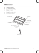
What is included • • • • • • The control module (2) 4-button transmitters A plug-in program switch A hood pinswitch A toggle override switch HX+ antenna receiver ������������������ ���������� ���������� ������������ ����������������� ������������ ���������������� ������� ������������ ������������� ������������������ ������������������ ������� HX Antenna receiver © 2008 Directed Electronics. All rights reserved.
Installation points to remember This product is designed for fuel-injected, automatic transmission vehicles only. Installing it in a standard transmission vehicle is dangerous and is contrary to its intended use. ➤ Intelli-Tach Intelli-Tach is a new feature for Ungo this year. It is the default RPM-sensing method for the new remote start system. Intelli-Tach gives the installer the performance of a hard wired tach wire, with the convenience of voltage sensing.
➤ Before beginning the installation • • • • • Please read this entire installation guide before beginning the installation. The installation of this remote start system requires interfacing with many of the vehicle’s systems. Many new vehicles use low-voltage or multiplexed systems that can be damaged by low resistance testing devices, such as test lights and logic probes (computer safe test lights). Test all circuits with a high quality digital multi-meter before making connections.
Finding the wires you need Important: Do not use a 12V test light or logic probe (computer safe test light) to locate these wires. All testing described in this manual assumes the use of a digital multimeter. ➤ Obtaining constant 12V We recommend two possible sources for 12V constant: The (+) terminal of the battery, or the constant 12V supply to the ignition switch. Always install a fuse within 12 inches of this connection.
How to find the starter wire with your multimeter: 1. 2. 3. Set to DCV or DC voltage (12V or 20V is fine). Attach the (-) probe of the meter to chassis ground. Probe the wire you suspect of being the starter wire. The steering column is an excellent place to find this wire. Remember you do not need to interrupt the starter, unless an optional anit-grind/starter disable relay is going to be installed. Hiding your starter kill relay and connections is always recommended. 4.
➤12V switched ignition wire The ignition wire is powered when the key is in the run or start position. This is because the ignition wire powers the ignition system (spark plugs, coil) as well as the fuel delivery system (fuel pump, fuel injection computer). Accessory wires lose power when the key is in the start position to make more current available to the starter motor. How to find (+)12V ignition with your multimeter: 1. Set to DCV or DC voltage (12V or 20V is fine). 2.
Note: Many Toyotas and other Asian vehicles, send a (-) signal from the switch to a relay. The relay then sends (+)12V to the bulbs. Whenever you have difficulty finding a (+) parking light wire near the switch, simply test the wires at any switch or control panel that is lit by the instrument panel lighting. Remember, you need a (+) parking light wire that does not vary with the dimmer setting. How to find a (+) parking light flash wire with your multimeter: 1.
be used. The tachometer wire will show between 1V and 6V AC. In multi-coil ignition systems, the system can learn individual coil wires. Individual coil wires in a multi-coil ignition system will register lower amounts of AC voltage. Also, if necessary, the system can use a fuel injector control wire for engine speed sensing. Common locations for a tachometer wire are the ignition coil itself, the back of the gauges, engine computers, and automatic transmission computers.
Making your wiring connections Before making your connections, plan how your wires will be routed through the vehicle. For instance, the red 12V constant input and the remote start ignition wires are often routed together to the ignition switch harness. In order to keep the wiring neat and make it harder to find, you may wish to wrap these wires together in electrical tape or conceal them in tubing similar to what the manufacturer used.
➤ Primary harness (H1) H1/1 LIGHT GREEN/ BLACK FACTORY ALARM DISARM H1/2 GREEN/WHITE FACTORY ALARM DISARM H1/3 YELLOW (+) IGNITION OUT (TO ALARM) H1/4 WHITE/BLUE (-) ACTIVATION INPUT H1/5 ORANGE (-) GROUND-WHEN-LOCKED H1/6 BROWN (-) HORN OUTPUT H1/7 RED/WHITE CHANNEL 2 (VALIDITY ONLY) H1/8 BLACK GROUND H1/9 WHITE (+/-) LIGHT FLASH ➤ Remote start harness, (H2) 5-pin connector H3/1 BLACK/WHITE (-) NEUTRAL SAFETY SWITCH INPUT H3/2 VIOLET/WHITE TACHOMETER INPUT WIRE H3/3 BROWN
➤ Heavy gauge relay harness H/1 PINK (+) (30 AMP) OUTPUT TO IGNITION CIRCUIT H/2 PURPLE (+) (30 AMP) OUTPUT TO STARTER CIRCUIT H/3 ORANGE (+) (30 AMP) OUTPUT TO ACCESSORY CIRCUIT H/4 RED (+) (30 AMP) HIGH CURRENT 12v INPUT H/5 PINK/WHITE (+) PROGRAMMABLE OUTPUT FOR ACCESSORY OR IGNITION RED (+) (30 AMP) HIGH CURRENT 12v INPUT ➤ Door lock harness, 3-pin connector 1 LIGHT BLUE (-) UNLOCK OUTPUT 2 EMPTY NOT USED 3 GREEN (-) LOCK OUTPUT © 2008 Directed Electronics. All rights reserved.
Wire connection guides ➤ Primary harness (H1), 9-pin connector H1/1 LIGHT GREEN/ BLACK (-) FACTORY ALARM DISARM Relay for Negative (-) Disarm Wire H1/2 GREEN/WHITE Relay for Positive (+) Disarm Wire FACTORY ALARM REARM OUTPUT This wire sends a negative pulse every time the remote start shuts down or when the doors are locked. This can be used to pulse the arm wire of the vehicle’s factory anti-theft device. Use a relay to send a (-) or (+) pulse to the arm wire.
H1/4 WHITE/BLUE REMOTE START (-) ACTIVATION INPUT This input comes from the factory set to 2 activation pulse. This means that it is necessary to have a two consecutive ground pulses on the white/blue wire for the remote start to activate or to deactivate. The same holds true for the remote control activation when set to a two pulse setting it is necessary to press the button twice for the remote start to activate or deactivate.
H1/7 RED/WHITE CHANNEL 2, (-) 200mA OUTPUT This wire produces a (-) 200mA output for progressive locks in which the driver door unlocks first and the remaining locks unlock with a second press of the unlock button. Warning! Never use this wire to drive anything but a relay or a low-current input, supplied output is only 200mA. Connecting directly to a solenoid, motor, or other high-current device will cause the module to fail.
H1/9 WHITE (+/-) LIGHT FLASH OUTPUT Important: Do NOT connect this wire to a negative vehicle light flash wire before changing the programming jumper to the negative polarity position or damage to the vehicle light circuit may occur. As factory configured, the H1/9 WHITE wire should be connected to the (+) parking light wire. If the light flash polarity jumper is moved to the (-) position (refer to the Programming Jumper section of this guide), this wire then supplies (-) 200mA output.
Connect this wire to the provided toggle (override) switch as shown in figure A. Connect the other wire from the toggle switch to the park/neutral switch in the vehicle. This wire will test with ground with the gear selector either in PARK or NEUTRAL. This will prevent the vehicle from accidentally being started while in a drive gear. This input MUST rest at ground in order for the remote start system to operate. Connected properly the vehicle will only start while in PARK or NEUTRAL.
H2/3 BROWN (+) BRAKE SWITCH INPUT, ZONE 1 This wire MUST be connected to the vehicle’s brake light wire. This is the wire that shows (+) 12V when the brake pedal is depressed. The remote start will be disabled or shut down any time the brake pedal is depressed. H2/4 GRAY (-) HOOD PIN SWITCH INPUT, ZONE 1 This wire MUST be connected to a hoodpin switch. This input will disable or shut down the remote start when the hood is opened. .
➤ Heavy gauge relay 5-pin connector H/1 PINK (+) IGNITION OUTPUT Connect this wire to the ignition wire in the vehicle. (See, Finding the wires you need section in this guide.) H/2 PURPLE (+) STARTER OUTPUT Connect this wire to the starter wire in the vehicle. ( See, Finding the wires you need.) H/3 ORANGE (+) ACCESSORY OUTPUT Connect this wire to the accessory wire in the vehicle that powers the climate control system. (See, Finding the wires you need).
Remove the two 30-amp fuses prior to connecting these wires and do not replace them until the satellite has been plugged into the control module. These wires are the source of current for pink ignition, orange accessory, purple starter, and the coils for the relays in the relay pack. They must be connected to a high current source. Since the factory supplies (+)12V to the key switch that is used to operate the motor, it is recommended that these wires be connected there.
Neutral safety switch interface Some vehicles combine the column shift mechanism and the mechanical neutral safety switch into one mechanical part. In these vehicles, it is impossible to interface the remote engine start system before the neutral safety switch. With this type of vehicle, if the vehicle is left in a drive gear and the remote engine start system is activated, the vehicle will move and may cause damage to persons or property.
without the key sense wire shutting down the unit prematurely. You must also connect the H2/4 BROWN (+) shut-down input to the yellow wire on the relay satellite ribbon cable. This prevents the remote engine start system from activating if the key is left in the “run” position. You must use diodes to isolate the ignition circuit from the brake switch circuit as shown in the diagram below.
general motors trucks, SUVs, and column shifting passenger cars PURPLE (-) START OUTPUT FROM 4-PIN HARNESS pre-1996 dodge dakota pickups with 2.5 liter motors 28 © 2008 Directed Electronics. All rights reserved.
Bypassing GM vehicle anti-theft systems (VATS) Vehicles with the GM VATS (Pass Key) systems have a resistor embedded in the ignition key. If the VATS decoder module does not measure the proper resistance when the vehicle is started, the starter and fuel pump may be disabled for up to ten minutes. The VATS wires will be two very light-gauge wires coming out of the steering column.
1995 and newer, VATS (immobilizers) 1995 and newer vehicle anti-theft systems (immobilizers) require a bypass module. The bypass module allows for easy interfacing, while still maintaining the OEM system’s integrity.
Other transponder-based systems include: Acura, BMW, Dodge/Chrysler/ Jeep, Ford, Honda, Infinity, Mazda, Mercedes, Mitsubishi, Nissan, Toyota, Volkswagon, and Volvo. PK-3 and the transponder-based systems use a transponder system that locks out the ignition and fuel system. This transponder system is comprised of two parts. The first part, the transceiver, circles the key switch and is activated when the key is placed in the key switch or turned to the run position.
Optional anti-grind relay The anti-grind relay prevents the starter from engaging if the ignition key is accidentally turned to the start position during remote engine start operation. 32 © 2008 Directed Electronics. All rights reserved.
Tachometer settings ➤ Intelli-Tach To program Intelli-Tach: 1. 2. 3. 4. After the install is complete, remote start the car. If the car does not start on the first attempt, let the remote start attempt again. Once the car starts, let it run until the parking lights come on. When the parking lights come on, shut off the remote start with the remote - that's it! Intelli-Tach is programmed. To reset Intelli-Tach, go into the remote programming grid and choose option #4.
➤ Tach learning To learn the tach signal: 1. Start the vehicle with the key. 2. Within 5 seconds, press and hold the Program switch. 3. After 3 seconds the LED will light constant when the tach signal is learned. 4. Release the Program switch. 34 © 2008 Directed Electronics. All rights reserved.
Programming jumpers ➤Light flash (+) / (-) polarity This jumper is used to determine the light flash output polarity. In the (+) position, the on-board relay is enabled and the unit will output (+)12V on the WHITE wire, H1/2. In the (-) position, the on-board relay is disabled. The WHITE wire, H1/2, will supply a 200mA (-) output suitable for driving factory parking light relays NOTE: For parking light circuits that draw 10 amps or more, the internal jumper must be switched to a (-) light flash output.
Transmitter/receiver Learn Routine™ The system comes with transmitters that have been taught to the receiver. The receiver can store up to 4 different transmitter codes in memory. Use the following learn routine to add transmitters to the system. The Program switch, plugged into the blue port, is used for programming. There is a basic sequence to remember whenever programming this unit: Key, Choose, Transmit and Release. 1. Insert the key. Turn the ignition to the ON position.
Channel Function 1 Auto Learn Standard Configuration (default) The auto learn configuration will automatically setup the remote button configuration. . 2 Delete remotes: This feature will erase all remotes from the memory of the system. This is useful in cases when a customer’s remote is lost or stolen. 3 Reset Features: This resets all the features of the system to the factory default settings.
For instance: You have programmed Channel 1 and you want to program Channel 3. Release the Program switch. Press it two times and release it to advance from Channel 1 to Channel 3. Now, press and hold the Program switch. The LED flashes three times. As before, do not release it. Learn Routine is exited if: • • • 38 The ignition is turned off The program switch is pressed too many times More than 25 seconds elapses between steps © 2008 Directed Electronics. All rights reserved.
Transmitter configurations The transmitters are programmed with the standard configuration by using the Auto Learn functions in the Transmitter/Receiver Learn Routine. For more information about the remote control functions, see the Owners Guide. ➤ Standard configuration operates Lock Panic Mode operates Unlock operates Remote start operates Channel 2 operates Timer Mode operates Rear defogger ������� ������ � and and ������� and ������� ����� ���� © 2008 Directed Electronics.
Operating settings learn routine The system features programmed dictates how the unit operates. Due to the number of features, the features have been divided into two menus. It is possible to access and change any of the feature settings using the Override switch. However, this process can be greatly simplified by using a ProSecurity Programmer. The remote coding may be locked if previously programmed using the ProSecurity Programmer.
3. Choose. Within 10 seconds, press and release the Program switch the number of times corresponding to the feature number you want to program and then press and hold the switch. . 4. Transmit. The transmitter is used to select the desired setting. Pressing button one changes the feature to the LED On setting (or flashes once for features with more than 2 settings). The horn honks once.
Feature menus The default settings are indicated in bold type. The number in parentheses indicates the number of times the LED flashes. ➤ Menu 1 Feature led on setting (default) led off setting Number (pRESS cHANNEL 1) (press channel 2) 1 Horn Honk Pulses OFF 20ms (2), 30ms (3), 40ms (4), 50ms (5) 2 Ignition Lock OFF Ignition Lock ON 3 Ignition Unlock OFF Ignition Unlock ON 4 Door Lock Pulse Duration 0.8 seconds 3.5 (2) , 0.4 (3) seconds 5 Unlock Output 1 pulse Unlock Output 2 pulses .
Feature descriptions The features of the system are described below. Default settings are in bold. The numbers in parentheses indicate the number of times the Status LED flashes. ➤ Menu 1 1-1 Horn Honk Pulses OFF: (1) No audible confirmation on Lock or Unlock. (2) 20ms horn honk, (3) 30ms horn honk, (4) 40ms horn honk, (5) 50ms horn honk 1-2 Ignition Locks OFF/ON : (2) When turned on Locks the doors three seconds after the ignition is turned On and the vehicles doors are closed.
1-7 Factory Alarm Disarm-With Unlock, Before Unlock, Remote Start Only: In the default setting the factory alarm disarm output will disarm the factory alarm system any time the button controlling Unlock or Remote Start is pressed. The “Before Unlock” output will disarm the factory alarm before the unlock output activates and when remote start is activated. The “Remote Start Only” will disarm the factory alarm only when the remote start is activated. 1-8 Factory Alarm Disarm 1 pulse: FAD 2 pulses.
➤ Menu 2 2-1 Engine Checking Intelli-Tach: (1) When set to “Intelli-Tach” (1) the remote start monitors the cranking voltage of the vehicle and sets it as a reference point. Fifteen seconds after the crank output sequence the remote start checks the voltage again to determine if the vehicle is running. When set to voltage, (2) the unit cranks the starter for the programmed time and then attempts to sense that the engine is running by detecting an increase in voltage.
2-5 Activation Pulse One: This allows the system to use 1, 2 or 3 pulses to activate the remote start sequence. The default setting is 1-pulse. Note: This setting affects both the input wire and the remote control. 2-6 2nd—IGNITION/ACCESSORY OUTPUT: This will allow the PINK/WHITE to be used as a 2nd ignition or a 2nd accessory. 2-7 Accessory State During Wait-To-Start OFF: This feature will allow the selection of the accessory output to be ON or OFF during wait-to-start. Use the two-honk setting for On.
Shutdown diagnostics To perform shutdown diagnostics: 1. With the ignition OFF, press and hold the Program switch. 2. Turn the ignition ON and then back OFF while holding the Program switch. 3. Release the Program switch. 4. Press and release the Program switch.
Rear defogger control The rear defogger output can be remotely turned on/off any time using the remote control. The default setting is On. To turn the rear defogger output OFF: 1. 2. 3. Press & release the and and buttons of the remote control. The parking lights will flash 2-times. The rear defogger output will no longer activate when the vehicle is remote engine started.
Timer mode By pressing the remote and buttons simultaneously the parking lights will flash 4 times and then start the vehicle and run for the set duration. The remote engine start can be shut off by the transmitter by pressing the remote engine start button and remain in timer mode, but if any other shut down zones or the ignition . ������� ������� 1. 2. 3. 4. 5. Press Timer mode buttons. The vehicle will confirm with 4 parking light flashes. A 1-second delay will start.
Safety check Before vehicle reassembly, the remote start system must be checked to ensure safe and trouble-free operation. The following test procedure must be used to verify proper installation and operation of the system. The installation must be completed before testing, including connection to the brake switch and hood switch. 1. 2. 3. Test the BRAKE shutdown circuit: With the vehicle in Park (P), activate the remote start system. Once the engine is running, press the brake pedal.
Troubleshooting • The ignition comes on, but the starter will not crank. Does it start with the key in the ignition? If so, does the vehicle have a VATS Pass-Key system? Will it start with the brake pedal depressed? (Make sure to disconnect the brake shutdown when performing this test.) If so, it may have a brake/ starter interlock. Is the correct starter wire being energized? Check by energizing it yourself with a fused test lead. • The starter cranks for six seconds but does not start.
• 1. 2. 3. 4. 5. 6. • 1. 2. 3. • 1. 2. 3. 52 The remote start will activate, but the starter never engages. Check for voltage on the purple starter wire two seconds after the remote start becomes active. If there is voltage present, skip to Step 4. If there is not voltage present, advance to Step 2. Check the 30A fuses. If the gray/black wait-to-start wire is detecting ground upon activation, the starter will not crank.
• 1. 2. • The vehicle starts, but will only run for 10 seconds. Is the remote start programmed for voltage sense? If this does not work, a tach wire should be used. Check shutdown diagnostics. The climate control system does not work while the unit is operating the vehicle. Either the wrong accessory wire is being energized or more than one ignition or accessory wire must be energized in order to operate the climate control system. © 2008 Directed Electronics. All rights reserved.
BROWN (-) horn output 54 D2D For connecting to external modules (+) ORANGE (-) ground-when-locked Wiring quick reference guide © 2008 Directed Electronics. All rights reserved.
© 2008 Directed Electronics. All rights reserved.
Get Started Get Protected Ungo ProSecurity 6200 Gateway Drive Cypress, CA 90630 www.Clarion.