
Installation manual

This vehicle security system requires interfacing with several of the vehicle's
factory wiring harnesses. Be sure to verify all connections with a digital multi-meter
prior to making connections. Failure to do this can result in serious damage to the
vehicles electrical system or deploying an air bag(s). It is also highly recommended
that all connections are soldered, rather than the use of T-Taps or Scotch Locks.
MS2106
5-BUTTON VEHICLE
SECURITY SYSTEM
WITH UNGO-NET INTERFACE
Installation Manual
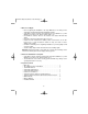
Table of Contents:
1. Ungo-NET Interface Introduction . . . . . . . . . . . . . . . . . . . . . . . 2
2. Before You Begin . . . . . . . . . . . . . . . . . . . . . . . . . . . . . . . . . . . 3
3. After the Installation is Complete . . . . . . . . . . . . . . . . . . . . . . . 3
4. System Contents . . . . . . . . . . . . . . . . . . . . . . . . . . . . . . . . . . . 3
5. Installation Tips and Suggestions . . . . . . . . . . . . . . . . . . . . . . . 4
6. Mounting Components . . . . . . . . . . . . . . . . . . . . . . . . . . . . . . . 5
7. Remote Transmitter Layout . . . . . . . . . . . . . . . . . . . . . . . . . . . 6
8. Wiring Information . . . . . . . . . . . . . . . . . . . . . . . . . . . . . . . . . . 7
9. Starter Disable Interface . . . . . . . . . . . . . . . . . . . . . . . . . . . . . 9
10. Plug-in Connectors . . . . . . . . . . . . . . . . . . . . . . . . . . . . . . . . 10
11. Programming Remote Transmitters . . . . . . . . . . . . . . . . . . . . 10
12. Programmable System Parameters . . . . . . . . . . . . . . . . . . . . 10
13. User Programmable Parameters . . . . . . . . . . . . . . . . . . . . . . 10
14. Installer Programmable Parameters . . . . . . . . . . . . . . . . . . . 12
15. System Test and Shock Sensor Adjustment . . . . . . . . . . . . . . 15
16. Parking Light Jumper Settings . . . . . . . . . . . . . . . . . . . . . . . . 16
17. Optional Circuit Interrupt . . . . . . . . . . . . . . . . . . . . . . . . . . . . 16
18. Dome Light Supervision Relay Diagram . . . . . . . . . . . . . . . . 17
19. Trunk/Hatch Release Diagram . . . . . . . . . . . . . . . . . . . . . . . 18
20. Door Lock Diagrams . . . . . . . . . . . . . . . . . . . . . . . . . . . . . . . 19
21. Driver’s Door Priority Wiring Diagram . . . . . . . . . . . . . . . . . . 24
22. Horn Honk Wiring Diagram . . . . . . . . . . . . . . . . . . . . . . . . . . 27
23. Status Indicator (LED) Function . . . . . . . . . . . . . . . . . . . . . . . 28
24. Siren Chirp Status . . . . . . . . . . . . . . . . . . . . . . . . . . . . . . . . .28
25. Troubleshooting . . . . . . . . . . . . . . . . . . . . . . . . . . . . . . . . . . 29
26. Warranty Information . . . . . . . . . . . . . . . . . . . . . . . . . . . . . . . 31
27. Wiring Diagram . . . . . . . . . . . . . . . . . . . . . . . . . . . . .back page
MS2106 install.qxd 6/25/2003 10:53 AM Page 1