2/1 CHANNEL POWER AMPLIFIER O P E R A T IO N IN S T A L L A T IO N MANUAL
DPX1001.2 Power System Amplifier TABLE OF CONTENTS Introduction . . . . . . . . . . . . . . . . . . . . . . . Description . . . . . . . . . . . . . . . . . . . . . . . Input Connections and Audio Controls . . . Connections for Power and Speakers . . . Applications . . . . . . . . . . . . . . . . . . . . . . . Installation . . . . . . . . . . . . . . . . . . . . . . . . Mounting Precautions . . . . . . . . . . . . . . . Wiring Precautions . . . . . . . . . . . . . . . . . . Setting the Gain . . . . . . . . .
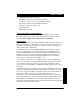
Owner’s Owner’sManual Manual • Gold-plated input/output connectors • Aluminum heat sink for efficient heat dissipation • Low profile, compact size for space limited installations • Wired remote Sub Level Control (BC2) included • Full range or low pass output mode • High level inputs • Built-in Subsonic filter ABOUT THE MANUAL AND WARRANTY To start enjoying your new Clarion two-channel amplifier, please read the instructions stated in this manual. Keep all instructions for future reference.
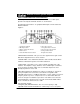
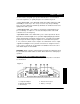
DPX1001.2 Power System Amplifier INPUT CONNECTIONS AND AUDIO CONTROLS The front panel of the DPX1001.2 contains connections for RCA Inputs, Speaker Level Inputs and Audio Controls as shown below. The RCA Input Connections are gold-plated RCA jacks and are labeled as RIGHT and LEFT. Figure 1- 1. Speaker Level Inputs 2. RCA Input Jacks 3. Remote Sub level Connector 4. Gain Control 5. Subsonic Filter Selection Switch 6. Bass Boost Control 7. Freq (Hz) Selection Control 8. X-Over Slope Select Switch 9.
Owner’s Manual Use this feature, along with your speaker manufacturer’s recommended crossover frequencies, to quickly design a more advanced system. • X-Over Slope Switch - This switch will change the X-Over between a 12db and 24dB per octave slope. The steep crossover slope keeps midrange tones out of the subwoofer and thereby eliminates an unnatural “nasal” tone quality in the audio system. • Output Mode Switch - This switch is to change the output between lowpass or fullrange.
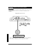
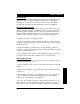
DPX1001.2 Power System Amplifier APPLICATIONS The Clarion DPX1001.2 2-channel car audio amplifier can be used in a variety of system applications. Here are some examples to help plan your own installation. Bridged-Mono Subwoofer System Set X-Over Mode to LP and adjust FREQ to speaker specifications. Figure 3 - In this application the amplifier is bridged for mono operation to drive a subwoofer. Minimum load in the bridged mode is 2 ohms.
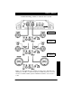
Owner’s Manual 2-Channel Full Range, Satellite, or Subwoofer Stereo System Set Amp Mode as shown Set Amp Mode as shown; adjust FREQ to speaker specifications. Set Amp Mode as shown; adjust FREQ to speaker specifications Figure 4 - In this application, the amplifier is used in stereo and drives two full-range (or satellite or subwoofer) speakers. NOTE: A passive crossover must be used with satellite speakers. Minimum load in the stereo mode is 1ohm.
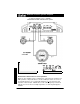
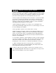
DPX1001.2 Power System Amplifier (Set INPUT SELECT Switch to STEREO) Mixed-Mode Satellite and Subwoofer System FREQ (Hz) L (mH) C (µF) 80 100 125 150 200 8.0 6.4 5.1 4.2 3.2 497 398 318 265 199 Set amp mode switch to fullrange NOTE: Chart values based on 4 ohm speakers. Figure 5 - The amplifier can be configured for a mixed-mode operation. The table provides component values to create a 6dB per octave crossover at specified frequencies.
Owner’s Manual INSTALLATION This section lists Mounting and Wiring Precautions for installing the Clarion DPX1001.2. These safeguards provide enough detail to complete the installation successfully. If you do not have the necessary skills, Clarion recommends consulting your authorized Clarion dealer for installation. MOUNTING PRECAUTIONS Although the Clarion DPX1001.
DPX1001.2 Power System Amplifier 5. Add an external fuse on the amplifier’s positive (+) power lead and connect it as close as possible to the vehicle’s (+) battery terminal. Use a fuse rated to the total current consumption of the amplifier(s). Adding an external fuse will protect the electrical system from short circuits that can cause a fire. 6. Refer to Figure 6 when making electrical connections. Connect the amplifier’s positive (+) lead via a fuse directly to the positive (+) terminal on the battery.
Owner’s Manual Figure 6. - Electrical connections for the DPX1001.
DPX1001.2 Power System Amplifier SETTING THE GAIN After completing the installation, follow these steps to set the Gain Control and then perform the Final System Checks. 1. Turn the Gain Control all the way counter-clockwise. 2. Turn the vehicle’s Ignition Switch to the ON position. Then turn the ON/OFF Switch on the source units to the ON position. Set all Tone or Equalization Controls to “flat” positions and turn Loudness off.
Owner’s Manual FINAL SYSTEM CHECKS 1. Start the engine and turn on the source unit. After a two-second delay, slowly increase the Volume Control and listen to the audio. If you hear any noise, static, distortion or no sound at all, check the connections, and also refer to Troubleshooting. Depending on your system design, the levels may become quite loud even at low Volume Control settings. Until you get an “audio feel” of the system’s power, use care when adjusting controls. 2.
DPX1001.2 Power System Amplifier Problem Audio lacks punch. Solution Speakers wired incorrectly, which causes cancellation of bass frequencies. Check polarity of wires from amplifier to each speaker as defined by the system design. Problem Amplifier fuse keeps blowing. Solution Incorrect wiring or short circuit. Review Installation and check all wiring connections. Problem Whining or ticking noise in the audio with engine on. Solution Amplifier is picking up alternator noise or radiated noise.
Owner’s Manual WARRANTY INFORMATION This product is warranted against all defects in material workmanship for a period of one year from the date of original purchase. Clarion ProAudio products except for speakers are covered by a two year warranty when installed by an authorized Clarion dealer. The conditions of this warranty and the extent of responsibility of Clarion Corporation under this warranty are as follows: 1. PROOF OF DATE OF PURCHASE WILL BE REQUIRED FOR WARRANTY SERVICE OF THIS PRODUCT.
Clarion Corporation of America 661 W. Redondo Beach Blvd. Gardena, CA 90247-4201 U.S.A. Tel 1.800.GO.CLARION www.clarion.com DPX1001.2 Rev.