apx-dpx-update.qxp 8/18/2004 8:46 AM Page 1 APX640.4/APX640.2/APX320.2/DPX1001.
apx-dpx-update.qxp 8/18/2004 8:46 AM Page 2 APX640.4/640.2/320.2/DPX1001.1 Dear Customer, Congratulations on your purchase of the world’s finest brand in the mobile electronic industry. At Clarion we are committed to high-quality music reproduction, and we are confident that you will be pleased with your purchase. Clarion’s extensive history in the mobile electronic industry translates into products that are built to the highest of standards.
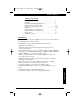
apx-dpx-update.qxp 8/18/2004 8:46 AM Page 3 Owner’s Owner’sManual Manual TABLE OF CONTENTS Introduction . . . . . . . . . . . . . . . . . . . . . . . . . . . . . . . . . . . . . . . . . 2 Description . . . . . . . . . . . . . . . . . . . . . . . . . . . . . . . . . . . . . . . . . 3 Installation, Mounting/Wiring Precautions . . . . . . . . . . . . . . . . . 4 Input Connections and Audio Control . . . . . . . . . . . . . . . . . . . . 5-8 Connections for Power and Speakers . . . . . . . . . . . . . . . .
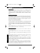
apx-dpx-update.qxp 8/18/2004 8:46 AM Page 4 APX640.4/640.2/320.2/DPX1001.1 INSTALLATION This section lists mounting and wiring precautions prior to installing the Clarion amplifier. These safeguards provide enough detail to complete an installation successfully. Do not attempt to install the amplifier yourself, if you do not have the necessary skills. Instead, see your authorized Clarion dealer for installation recommendations.
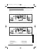
apx-dpx-update.qxp 8/18/2004 8:46 AM Page 5 Owner’s Manual INPUT CONNECTIONS AND AUDIO CONTROL Clarion amplifiers contain connections for RCA Inputs and Audio Control as shown below. 4 1 6 2 INPUT L 8 3 0 55 15 550 7 5 9 CROSSOVER 110 APX320.2 240 dB 4V-8V 2V-4V 0.2V-2V R 330 Hz FREQ RANGE X1 X10 HIGH Level OFF HP LP L & R (MONO) BRIDGED (R IN) L STEREO R Figure 1-1 APX320.2 Input Connections and Audio Control 4 1 6 2 INPUT 9 APX640.2 240 15 R 4V-8V 2V-4V 0.
apx-dpx-update.qxp 8/18/2004 8:46 AM Page 6 APX640.4/640.2/320.2/DPX1001.1 INPUT CONNECTIONS AND AUDIO CONTROL Clarion amplifiers contain connections for RCA Inputs and Audio Control as shown below. 17 5 3 2 INPUT FRONT (2 CH. IN) REAR 0.2V-0.6V 0.6V-4V 2V-8V FRONT GAIN L HIGH Level 6 REAR GAIN 0 SOURCE SELECT 2 CH. BASS BOOST 330 55 8 X1 X10 330 LP OFF 28 24 9 23 REAR HIGH Level L & R MONO BRIDGED (R L IN) STEREO + L + RHP 240 550 LP OFF APX640.
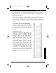
apx-dpx-update.qxp 8/18/2004 8:46 AM Page 7 Owner’s Manual The Input Connections are gold-plated RCA Jacks. The Gain Controls provide a wide adjustment range to accommodate output levels from any source unit brand. Precise Frequency Selector The filter frequency markings on the front panel of the amplifier are for reference purposes. If you would like to select the filter frequency with a higher level of precision, consult the chart in Figure 3 on this page.
apx-dpx-update.qxp 8/18/2004 8:46 AM Page 8 APX640.4/640.2/320.2/DPX1001.1 • Load Selector Please note that when configuring the DPX1001.1 amplifier, the LOAD SELECTOR switch must be set in the correct position in order for the amplifier to function properly. Please refer to the chart below for specific settings.
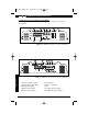
apx-dpx-update.qxp 8/18/2004 8:47 AM Page 9 Owner’s Manual CONNECTIONS FOR POWER AND SPEAKERS The rear panel of Clarion’s amplifiers contain power and speaker connections as shown below. 3 4 L 4 2 MIN + MIN 6 5 7 8 R 2 MIN + 30 AMP MAX APX320.2 Figure 4-1 APX320.2 Connections for Power and Speakers 3 4 L 4 2 MIN + MIN 6 5 7 8 R 2 MIN + 25x2 AMP MAX APX640.2 1. Left Front Speaker Output 2. Right Front Speaker Output 3. Left Speaker Output 4. Right Speaker Output 5.
apx-dpx-update.qxp 8/18/2004 8:47 AM Page 10 APX640.4/640.2/320.2/DPX1001.1 CONNECTIONS FOR POWER AND SPEAKERS The rear panel of Clarion’s amplifiers contain power and speaker connections as shown below. 1 6 2 5 7 8 R L 4 2 MIN + MIN 2 MIN + 25x2 AMP MAX APX640.4 FRONT REAR 9 10 Figure 5-1 APX640.4 Connections for Power and Speakers 4 3 1 MIN 1 MIN POWER 5 7 GND REM +12V DPX1001.1 RIGHT LEFT USA 6 BRIDGED 2 MIN CONNECTIONS Figure 5-2 DPX1001.
apx-dpx-update.qxp 8/18/2004 8:47 AM Page 11 Owner’s Manual Bridged-Mono Subwoofer System L 4 2 MIN + MIN R 2 MIN + 30 AMP MAX BASS BOOST CROSSOVER 110 55 0 240 550 15 APX320.2 330 dB FREQ RANGE FREQ Hz L & R (MONO) OFF X1 HP X10 BRIDGED (R IN) STEREO LP Set X-Over Mode to LP and adjust frequency to subwoofer specifications. R 2 MIN + 25x2 AMP MAX BASS BOOST 0 CROSSOVER 110 55 240 550 15 APX640.
apx-dpx-update.qxp 8/18/2004 8:49 AM Page 12 APX640.4/640.2/320.2/DPX1001.1 2-Channel Full-Range or Subwoofer System (APX320.2 or APX640.2) R L 4 2 MIN + MIN 2 MIN + 30 AMP MAX L - Full Range APX320.
apx-dpx-update.qxp 8/18/2004 8:51 AM Page 13 Owner’s Manual 4-Channel High Power System R L 4 2 MIN + MIN 2 MIN + 25x2 AMP MAX APX640.4 FRONT REAR FL - Full Range RR - Full Range FR - Full Range RL - Full Range FREQ Hz 110 55 FREQ Hz 110 HP 240 550 240 330 REAR X1 X10 LP OFF 330 APPLICATIONS 550 FREQ RANGE 55 Figure 8 - In this application, the APX640.4 is used as a 4-channel amplifier to drive four full-range speakers in stereo.
apx-dpx-update.qxp 8/18/2004 8:52 AM Page 14 APX640.4/640.2/320.2/DPX1001.1 1 MIN 1 MIN POWER GND REM +12V DPX1001.1 RIGHT LEFT BRIDGED 2 MIN USA XOVER FREQ Hz 55 550 110 XOVER SLOPE 240 330 12dB 24 dB R - Subwoofer CONNECTIONS L - Subwoofer Figure 9 - In this application, the DPX1001.1 is used to drive a pair of subwoofers.
apx-dpx-update.qxp 8/18/2004 8:52 AM Page 15 Owner’s Manual SETTING THE GAIN After completing the installation, follow these steps to set the Gain Control and then perform the Final System Checks. 1. Turn the Gain Control all the way counter-clockwise. 2. Select the proper input voltage as described on page 7, (Gain Control with Selectable Input Voltage) 3. Turn the vehicle’s Ignition Switch to the ON position. Then turn the ON/OFF Switch on the source unit to the ON position.
apx-dpx-update.qxp 8/18/2004 8:52 AM Page 16 APX640.4/640.2/320.2/DPX1001.1 FINAL SYSTEM CHECKS 1. Start the engine and turn on the source unit. After a two-second delay, slowly increase the volume control and listen to the audio. If you hear any noise, static, distortion or no sound at all, check the connections, and also refer to troubleshooting section below. Depending on your system design, the levels may become quite loud even at low volume control settings.
apx-dpx-update.qxp 8/18/2004 8:52 AM Page 17 Owner’s Manual Problem Amplifier fuse keeps blowing. Solution Incorrect wiring or short circuit: Review Installation and check all wiring connections. Problem Whining or ticking noise in the audio with engine on. Solution Amplifier is picking up alternator noise or radiated noise: Turn down input gain and move audio cables away from power wires. Check power and ground connections on amplifier and install an in-line noise filter on source unit’s power wire.
apx-dpx-update.qxp 8/18/2004 8:52 AM Page 18 WARRANTY INFORMATION This product is warranted against all defects in material workmanship for a period of one year from the date of original purchase. Clarion ProAudio products, except for speakers, are covered by a two-year warranty when installed by an authorized Clarion dealer. The conditions of this warranty and the extent of responsibility of Clarion Corporation under this warranty are as follows: 1.
apx-dpx-update.qxp 8/18/2004 8:52 AM Page 19 Clarion Canada Inc. 2239 Winston Park Drive Oakville, ON L6H 5R1 1-800-668-5612 www.clarion.com Amp Manual - Rev.
OWNER’S MANUAL SUPPLEMENT CLARION DPX1001.1 Please note that when configuring the DPX1001.1 amplifier, the LOAD SELECTOR switch must be set in the correct position in order for the amplifier to function properly. Please refer to the chart below for specific settings.