
Installation manual


clanon
4
Channel
Power
System
Amplifier
6.
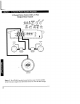
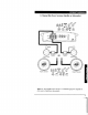
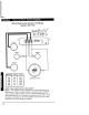
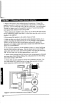
Refer to the Figure 8 when maklllg electncal connectIOns. Connect the
amplifier's positive (+) lead
Via
a fuse directly to the positive (+) termmal on
the battery. Do not connect this
Wire
to the car's fuse panel. Use red-lllsulated
la-gauge (or larger)
WIre
for the amplifier's
pOSItive
(+) power lead and the
same-gauge black msulated
WIre
for the ground.
7 When replacmg the amplifier's fuse, always use one havmg the same current
ratmg. SubstItutmg a hIgher-rated fuse or a slow-blow type can result m senous
damage to the amplifier.
8.
Never ground the speakers to the vehIcle chassis or body.
9 Make sure that your vehIcle's electncal system (alternator, battery, etc.)
IS
capable
of
handling the additional load.
If
you are plannlllg a multI-amplifier
system, you may need to add a second battery and possibly upgrade the
alternator with a hIgher-output rated model. Consult your authonzed Clanon
dealer for recommendatIOns.
10.
To
avoId
nOIse
problems, run the amplifier's posItIve (+) power lead along
one sIde
of
the vehIcle to the battery. Run the remote tum-on
WIre
and RCA
audio cables down the center, and route the speaker
WIres
along the remammg
sIde.
If
WIres
must cross, run them perpendicular to each other.
11. When creatmg passage holes for the power
WIre,
use grommets to elimmate
any sharp edges created durmg drilling.
ThIS
will protect the
WIre
from belllg
mcked and causmg a short
CIrcUIt.
12. Extra cable can cause sIgnal loss and act as an "antenna" for
nOIse.
Use
only hIgh-quality RCA cables that are no longer than necessary to make a
direct connectIOn wIth the source umt or equalizer.
Lefl Fronl Speaker
LeflFrontSpeaker+
Le1tRearSpeakef+-
;@,
~,
..
__
----IJ\,
~
"
Figure 8 - Electncal connectIOns for the APX400.4
12