
User's Manual

ClarIDy UHF USB Reader Demo Program for Linux
20/28 © Copyright 2008 ClarIDy Solutions, Inc. All rights reserved.
3.2.4 Filter Inventory
Follow the instructions step by step as following:
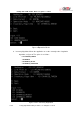
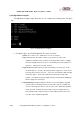
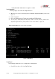
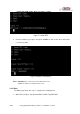
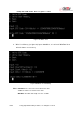
1. When the user select "4: Filter Inventory", the system shows the input dialogs:
“Mask bank”, “Mask start”, “Mask Length”, “Mask data”, “match or unmatched” and
“interval time”, as figure 21.
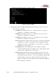
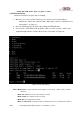
2. Place the RFID tag in the RF field of the ClarIDy UHF RFID Reader.
3. The PC (“PC”), EPC (EPC), CRC16 (CRC), number of reads (“Count”), and Receive
Signal Strength Indicator (“RSSI”) will be shown on the table, as Figure 21.
Figure 21
Filter Inventory
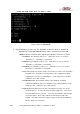
Note :
Mask bank: The memory bank to match against ( 0: Reserved, 1: EPC, 2: TID, 3: USER
Memory).
Mask start offset: The offset of the first byte to match.
Mask Length: The number of bits in the mask.
Mask data: The byte pattern to match.
Match or unmatched: selected to match or unmatched (0: none 2: unmatched, 3: match ).