
User Manual


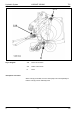


Table Of Contents
- Hydraulic System Variant 260/280
- Contents
- Chapter 1 Overall hydraulic system circuit diagram
- Chapter 2 Function
- Chapter 3 Valve components
- 3.1 Main valve block – without active hydraulic system Hydraulic circuit diagram
- 3.2 Baling chamber service shut-off valve – without active hydraulic system
- 3.3 Lock-up valve unit (734)
- 3.4 Pressure relief valve (754), Baling pressure build-up solenoid valve (Y50) without active hydraulic system
- 3.5 Flow controllers (755, 756)
- 3.6 Rotor cut-out clutch Shut-off tap (627)
- 3.7 ROTO CUT knife support IN/OUT solenoid valve (Y54/Y55)
- 3.8 Main valve block – with active hydraulic system
- Index
- 0299 256.1

TIC VARIANT 260/280 Hydraulic System
11/04 var-h 49
Key to diagram:
1 Friction disc
2 Bolts
3, 4 Sprocket
5 U-plate
6 Bolts
7 Port
8 Pressure spring
9 Sprocket
Description of function:
Friction disc (1) Ensures rotor rotation while clutch is disengaged. This avoids net damage.
Bolts (2) are bolted to the U-shaped sheet metal (5) and connect the sprockets
(3 and 4) when the clutch is closed.
Sprocket (3) Is welded to sprocket (9).
Sprocket (4) Bale chamber drive
U-plate (5)
- The bolts (2) are bolted here
- Is loaded by the pressure springs (8) so that the bolts (2) remain
engaged = clutch engaged.
Bolts (6) Is bolted to the transmission input shaft.
Port (7) Hydraulic connection to the shut-off valve and to the rotor cut-out clutch /
2
nd
belt drive (item 627, see circuit diagram).
Pressure spring (8) 3 pieces distributed around the circumference. They load the U-shaped
sheet metal (5).
Sprocket (9) Pick-up rotor drive
Clutch disengage function Pressurized oil enters via port (7) and acts on the top side of bolt (6).
The U-plate (5) performs a stroke of approx. 12 - 14 mm.
As the bolts (2) are bolted to the U-plate, sprocket (4) is disengaged by
sprocket (9). Sprocket (9) may be freely rotated on the bearing bushing.
Clutch engage function No pressurized oil in port (7). The compression springs (8) press on the
bolts (6) connecting the two sprockets (4 and 9) with one another via the
U-shaped sheet metal (5).