
User Manual


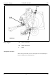


Table Of Contents
- Hydraulic System Variant 260/280
- Contents
- Chapter 1 Overall hydraulic system circuit diagram
- Chapter 2 Function
- Chapter 3 Valve components
- 3.1 Main valve block – without active hydraulic system Hydraulic circuit diagram
- 3.2 Baling chamber service shut-off valve – without active hydraulic system
- 3.3 Lock-up valve unit (734)
- 3.4 Pressure relief valve (754), Baling pressure build-up solenoid valve (Y50) without active hydraulic system
- 3.5 Flow controllers (755, 756)
- 3.6 Rotor cut-out clutch Shut-off tap (627)
- 3.7 ROTO CUT knife support IN/OUT solenoid valve (Y54/Y55)
- 3.8 Main valve block – with active hydraulic system
- Index
- 0299 256.1

TIC VARIANT 260/280 Hydraulic System
11/04 var-h 43
Key to diagram:
755 Flow controller
756 Flow controller
M
P, X Port
V Connection
Y50 Baling pressure build-up solenoid valve
Description of function:
Open tailgate:
- Volume flow enters via port (P) and flows through flow controller
(756) from the spring side; flow controller (756) does not control the
flow.
- Volume flow flows via the connecting channel to the face end of the
flow controller (755).
- The flow controller (755) controls the volume flow to 50 l/min.
- The volume flow flows via port (V) to the rotary disc valve of the shut-
off tap and continues into the piston top spaces of the tailgate
cylinders.
Close tailgate:
- Volume flow enters via port (V) and flows through flow controller
(755) from the spring side; flow controller (755) does not control the
flow.
- Volume flow flows via the connecting channel to the face end of the
flow controller (756).
- The flow controller (756) controls the volume flow to 18 l/min.
- The volume flow flows to the tractor via port (P).
Baling pressure build-up
solenoid valve (Y50)
- limits the pressure in the tensioning arm circuit and thus controls the
baling pressure.
- is controlled by the electronic box (the desired baling pressure is set
by a potentiometer).
- when the power supply fails, the highest baling pressure is reached.