
User Manual


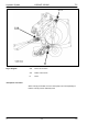


Table Of Contents
- Hydraulic System Variant 260/280
- Contents
- Chapter 1 Overall hydraulic system circuit diagram
- Chapter 2 Function
- Chapter 3 Valve components
- 3.1 Main valve block – without active hydraulic system Hydraulic circuit diagram
- 3.2 Baling chamber service shut-off valve – without active hydraulic system
- 3.3 Lock-up valve unit (734)
- 3.4 Pressure relief valve (754), Baling pressure build-up solenoid valve (Y50) without active hydraulic system
- 3.5 Flow controllers (755, 756)
- 3.6 Rotor cut-out clutch Shut-off tap (627)
- 3.7 ROTO CUT knife support IN/OUT solenoid valve (Y54/Y55)
- 3.8 Main valve block – with active hydraulic system
- Index
- 0299 256.1

TIC VARIANT 260/280 Hydraulic System
11/04 var-h 41
Key to diagram:
102-2 Filter
731-4 Non-return valve
754 Pressure relief valve
E Port
M Solenoid coil
Y50 Baling pressure build-up solenoid valve
Description of function:
Non-return valve (731-4) shuts off the pre-pressurizing circuit against the filter circuit.
Pressure relief valve (754) Maintains the pressure in the tensioning arm circuit at 10 bar.
Port (E) to the ram spaces of the tensioner cylinders.
Solenoid coil (M) Solenoid coil of Baling pressure build-up solenoid valve (Y50)
Baling pressure build-up
solenoid valve (Y50)
- limits the pressure in the tensioning arm circuit and thus controls the
baling pressure.
- Is actuated by the electronic box (the desired baling pressure is set
with a potentiometer).
- When power supply fails, the highest baling pressure is reached.