
User Manual


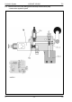
Table Of Contents
- Hydraulic System Variant 260/280
- Contents
- Chapter 1 Overall hydraulic system circuit diagram
- Chapter 2 Function
- Chapter 3 Valve components
- 3.1 Main valve block – without active hydraulic system Hydraulic circuit diagram
- 3.2 Baling chamber service shut-off valve – without active hydraulic system
- 3.3 Lock-up valve unit (734)
- 3.4 Pressure relief valve (754), Baling pressure build-up solenoid valve (Y50) without active hydraulic system
- 3.5 Flow controllers (755, 756)
- 3.6 Rotor cut-out clutch Shut-off tap (627)
- 3.7 ROTO CUT knife support IN/OUT solenoid valve (Y54/Y55)
- 3.8 Main valve block – with active hydraulic system
- Index
- 0299 256.1

TIC VARIANT 260/280 Hydraulic System
11/04 var-h 37
Key to diagram:
626 Baling chamber service shut-off valve
I, II Lever positions
Description of function:
Position I:
The shut-off valves (626 C and 626 D) provide a connection to the tailgate
cylinders. The shut-off valve (626 E) has shut off the connection to the
tensioning cylinders.
Position II:
The shut-off valves (626 C and 626 D) have shut off the connection to the
tailgate cylinders. The shut-off valve (626 E) has opened the connection to
the tensioning cylinders.