
User Manual
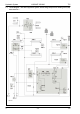


Table Of Contents
- Hydraulic System Variant 260/280
- Contents
- Chapter 1 Overall hydraulic system circuit diagram
- Chapter 2 Function
- Chapter 3 Valve components
- 3.1 Main valve block – without active hydraulic system Hydraulic circuit diagram
- 3.2 Baling chamber service shut-off valve – without active hydraulic system
- 3.3 Lock-up valve unit (734)
- 3.4 Pressure relief valve (754), Baling pressure build-up solenoid valve (Y50) without active hydraulic system
- 3.5 Flow controllers (755, 756)
- 3.6 Rotor cut-out clutch Shut-off tap (627)
- 3.7 ROTO CUT knife support IN/OUT solenoid valve (Y54/Y55)
- 3.8 Main valve block – with active hydraulic system
- Index
- 0299 256.1

TIC VARIANT 260/280 Hydraulic System
11/04 var-h 19
Swinging out the knife
support
The single-acting tractor control unit is set to the "Lower" position – port
(801-1) is connected to the tank.
When actuating the "Swing out knife support" button, the 2/3 way
directional control valve (Y54) is energized.
The baled material loads the ROTOCUT knives hydraulic cylinders (336),
making volume flow flow into the tank from the ram spaces via the
energized 2/3 way valve (Y54), the unenergized 2/3 way valve (Y55) and
port (801-1).