
User Manual
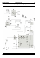


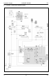


Table Of Contents
- Hydraulic System Variant 260/280
- Contents
- Chapter 1 Overall hydraulic system circuit diagram
- Chapter 2 Function
- Chapter 3 Valve components
- 3.1 Main valve block – without active hydraulic system Hydraulic circuit diagram
- 3.2 Baling chamber service shut-off valve – without active hydraulic system
- 3.3 Lock-up valve unit (734)
- 3.4 Pressure relief valve (754), Baling pressure build-up solenoid valve (Y50) without active hydraulic system
- 3.5 Flow controllers (755, 756)
- 3.6 Rotor cut-out clutch Shut-off tap (627)
- 3.7 ROTO CUT knife support IN/OUT solenoid valve (Y54/Y55)
- 3.8 Main valve block – with active hydraulic system
- Index
- 0299 256.1

Hydraulic System VARIANT 260/280 TIC
18 var-h 11/04
Relieving the belts during
maintenance work in the
baling chamber
- Switch on control box (baler CCT) so the baling pressure build-up
solenoid valve (Y50) is energized.
- Disengage the p.t.o. shaft.
- Open the tailgate as far as necessary and secure it.
- Actuate the baling chamber service shut-off valve (626):
The shut-off taps (626 C) and (626 D) of the tailgate are now shut off and
the shut-off tap (626 E) is open.
Oil flows into valve block 6 (port P) via port (801-2 A), filter (102-1) and
the rotor clutch / 2
nd
belt drive shut-off tap (627).
Volume flow continues to flow via filter (102-2), non-return valve (731-4)
and port (E) into the ram spaces of hydraulic cylinders (346-1, 346-2 and
345) through the open shut-off tap (626 E).
The cylinders extend and the belts are relieved.
The volume flow displaced from the rod spaces of hydraulic cylinders
(346-1, 346-2 and 345) flows to the baling pressure build-up solenoid
valve (Y50) via port (X). This valve is electronically regulated to 0 bar
when the tailgate is open and oil may therefore flow freely through it.
The rod spaces and the ram spaces of the belt tensioner cylinders (346-1,
346-2 and 345) are now connected with each other.
There is the same pressure in both cylinder spaces, but since the greater
force is generated on the ram surface (greater by the force of the rod
surface), the cylinders extend and relieve the belts.
Tensioning the belts The baling chamber service shut-off valve still is in the "Tailgate blocked"
position; now the double-acting control unit provided on the tractor is set
to the "Lower" position
The hydraulic cylinders (346-1, 346-2 and 345) are retracted by springs
on the left baler side.
The volume flow displaced from the ram spaces flows via port (E) and
uses two different paths, depending on the pressure:
- when the pressure is above 10 bar, it flows into the tank via the
pressure relief valve (754), the flow controllers (756 and 755), port
(P) and port (801-2 A).
- when the pressure is below 10 bar, the non-return valves (722-1,
722-2 and 722-3) open and provide volumetric compensation so that
the tensioning arms can return to their initial position faster.
When maintenance work is finished, the tailgate is closed; during this, the
belts must be driven so that they will not be squeezed.
Swinging in the knife
support
When actuating the "Swing in knife support" button, the 2/3 way
directional control valve (Y55) "ROTOCUT knives IN" is energized.
Volume flow flows into the ROTOCUT knives hydraulic cylinders (336) via
port (801-1) and the energized 2/3 way valve.
The ROTOCUT knives hydraulic cylinders (336) extend and swing in the
knife support.
The extended ROTOCUT knives hydraulic cylinders (336) are kept in thei
r
position by the non-return valve inside the 2/3 directional control valve
(Y54).