
User Manual
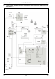


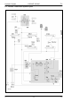


Table Of Contents
- Hydraulic System Variant 260/280
- Contents
- Chapter 1 Overall hydraulic system circuit diagram
- Chapter 2 Function
- Chapter 3 Valve components
- 3.1 Main valve block – without active hydraulic system Hydraulic circuit diagram
- 3.2 Baling chamber service shut-off valve – without active hydraulic system
- 3.3 Lock-up valve unit (734)
- 3.4 Pressure relief valve (754), Baling pressure build-up solenoid valve (Y50) without active hydraulic system
- 3.5 Flow controllers (755, 756)
- 3.6 Rotor cut-out clutch Shut-off tap (627)
- 3.7 ROTO CUT knife support IN/OUT solenoid valve (Y54/Y55)
- 3.8 Main valve block – with active hydraulic system
- Index
- 0299 256.1

TIC VARIANT 260/280 Hydraulic System
11/04 var-h 17
Description of function:
Close tailgate Volume flow enters the valve block (6, port T) via port (801-2 B) and flows
to the lock-up valve unit non-return valve (734-1). The lock-up valve unit
is opened.
Pressurized oil flows into the rod spaces of hydraulic cylinders (318-1 and
318-2) via the opened lock-up valve unit non-return valve (734-1) and
port D.
The volume flow displaced from the ram spaces of hydraulic cylinders
(318-1 and 318-2) flows into the tank via the shut-off taps (626 C and D),
the flow controllers (756 and 755), the shut-off tap (627) and filter (102-1).
The flow controller controls the returning volume flow to 18 l/min., making
the tailgate closing velocity lower than the opening velocity.
Baling Baled material pulls the hydraulic cylinders (346-1, 346-2 and 345) to the
outside by means of the tensioning arms. This builds up baling pressure
in the rod spaces of these cylinders.
The pressure can be read on pressure gauge (912 baling pressure).
The baling pressure enters valve block (6) via input (X).
The baling pressure is applied at the baling pressure build-up solenoid
valve (Y50).
When the set baling pressure has been reached, the baling pressure
build-up solenoid valve (Y50) opens, making volume flow flow via port (E)
into the ram sides of hydraulic cylinders (346-1, 346-2 and 345).
The hydraulic accumulator (513) compensates the volumetric difference.
Open tailgate Volume flow flows into valve block 6 (port P) via port (801-2 A), filter
(102-1) and the rotor clutch / 2
nd
belt drive shut-off tap (627).
The volume flow flows via the open shut-off taps (626C and 626D) into
the ram spaces of hydraulic cylinders (318-1 and 318-2), via ports (A and
B). During this process, the flow rate is regulated to 50 l/min. by the flow
controllers (756 and 755).
At the same time, the lubricating oil pump (232) is supplied.
Pressurized oil is tapped directly downstream of inlet (P) of valve block (6)
which opens the lock-up valve unit non-return valve (734-1).
The volume flow displaced from the rod spaces of hydraulic cylinders
(318-1 and 318-2) flows through the open lock-up valve unit non-return
valve (734-1) and port (T) to the quick release coupling (801-2 B).
Downstream of the rotor clutch / 2nd belt drive shut-off tap (627),
pressurized oil flows to the rotor cut-out clutch (338) and to the drive
clutch (370) for roller 3.
The clutches open so that the rotor and the drive of roller 3 are switched
off while the tailgate is opened.