
User Manual

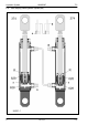

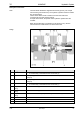
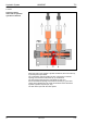

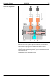

Table Of Contents
- Technical Systems Hydraulic System UNIWRAP
- Contents
- 1 Hydraulic circuit diagram
- 1.1 Hydraulic circuit diagram up to serial no.: 72600130
- 1.2 Hydraulic circuit diagram from machine no.: 72600131, with tipping cradle service shut-off valve (631)
- 1.3 Hydraulic circuit diagram from machine no.: 72600531, with film clamping cutters flow divider (769)
- 1.4 Hydraulic circuit diagram from serial no.: 72601047, with valve combination (630, 706, 769), without 3-stage restrictor (645)
- 1.5 Hydraulic circuit diagram from serial no.: 72601047, with valve combination (630, 706, 769), with 3-stage restrictor (645)
- 2 Pre-conditions for use
- 3 Valve block
- 4 Individual components
- 4.1 Input pressure balance (763)
- 4.2 Circulation shut-off valve (Y77-2)
- 4.3 Wrapping arm control unit (Y133)
- 4.4 Tipping cradle control unit (Y135 / Y136)
- 4.5 Wrapping table control unit (Y137 / Y138)
- 4.6 Clamping cutters control unit (Y139 / Y140)
- 4.7 Flow controller (630)
- 4.8 Pressure relief valve (706)
- 4.9 Wrapping arm motor (234)
- 4.10 Wrapping table motor (235)
- 4.11 Tipping cradle service shut-off valve (631)
- 4.12 Film clamping cutters hydraulic cylinder (374)
- 4.13 Film clamping cutters flow divider (769)
- 4.14 Wrapping arm motor valve block (4)
- 4.15 3-stage restrictor
- 4.16 Valve combination (7)
- 4.17 Manifold (8)
- 0293 522.0

Hydraulic System UNIWRAP TIC
86 UNI-h-Kap4 11/04
Function
Open film cutters
while load on hydraulic
cylinders is identical
When the load on the hydraulic cylinders is identical, the control rams (1,
4) are subject to equal loads.
The compression springs position the two control rams so that the
opening cross-sections of the bores (2, 3) are identical.
The total volume flow enters the flow divider via port (P1).
Due to the identical opening cross-sections of bores (2, 3), the total
volume flow is divided into two equal volume flows which extend the
hydraulic cylinders via ports (P2, P3).
The film cutters open with the same speed.