
User Manual

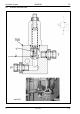


Table Of Contents
- Technical Systems Hydraulic System UNIWRAP
- Contents
- 1 Hydraulic circuit diagram
- 1.1 Hydraulic circuit diagram up to serial no.: 72600130
- 1.2 Hydraulic circuit diagram from machine no.: 72600131, with tipping cradle service shut-off valve (631)
- 1.3 Hydraulic circuit diagram from machine no.: 72600531, with film clamping cutters flow divider (769)
- 1.4 Hydraulic circuit diagram from serial no.: 72601047, with valve combination (630, 706, 769), without 3-stage restrictor (645)
- 1.5 Hydraulic circuit diagram from serial no.: 72601047, with valve combination (630, 706, 769), with 3-stage restrictor (645)
- 2 Pre-conditions for use
- 3 Valve block
- 4 Individual components
- 4.1 Input pressure balance (763)
- 4.2 Circulation shut-off valve (Y77-2)
- 4.3 Wrapping arm control unit (Y133)
- 4.4 Tipping cradle control unit (Y135 / Y136)
- 4.5 Wrapping table control unit (Y137 / Y138)
- 4.6 Clamping cutters control unit (Y139 / Y140)
- 4.7 Flow controller (630)
- 4.8 Pressure relief valve (706)
- 4.9 Wrapping arm motor (234)
- 4.10 Wrapping table motor (235)
- 4.11 Tipping cradle service shut-off valve (631)
- 4.12 Film clamping cutters hydraulic cylinder (374)
- 4.13 Film clamping cutters flow divider (769)
- 4.14 Wrapping arm motor valve block (4)
- 4.15 3-stage restrictor
- 4.16 Valve combination (7)
- 4.17 Manifold (8)
- 0293 522.0

TIC UNIWRAP Hydraulic System
11/04 UNI-h-Kap4 71
Key to diagram:
P Input for total volume flow = Return oil from wrapping arm
hydraulic motor (approx. 17 l/min)
A Port
Constant flow output to wrapping table hydraulic motor.
B Port
Residual flow output to tank.
E Adjusting screw
Adjusts the pre-stress of the pressure spring
1 Orifice plate
In the control piston (3), produces the pressure difference ∆p
which determines the constant flow at port A.
2 Control edge
Controls the passage to port B
3 Control piston
- is pushed to the left-hand stop by the pressure spring when
no volume flow is flowing
- is moved by the pressure difference Dp at the orifice plate (1)
when volume flow flows.
4 Bore
The constant flow to port A flows via this bore.
6 Connecting bore
Directs the pressure behind the orifice plate into the spring
space
630 Flow controller
Divides the total volume flow (port P) into:
- a constant flow (port A) which drives the wrapping table
hydraulic motor and
- a residual flow (port B) which is directed into the tank.