
User Manual
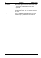
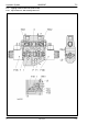

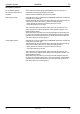


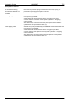
Table Of Contents
- Technical Systems Hydraulic System UNIWRAP
- Contents
- 1 Hydraulic circuit diagram
- 1.1 Hydraulic circuit diagram up to serial no.: 72600130
- 1.2 Hydraulic circuit diagram from machine no.: 72600131, with tipping cradle service shut-off valve (631)
- 1.3 Hydraulic circuit diagram from machine no.: 72600531, with film clamping cutters flow divider (769)
- 1.4 Hydraulic circuit diagram from serial no.: 72601047, with valve combination (630, 706, 769), without 3-stage restrictor (645)
- 1.5 Hydraulic circuit diagram from serial no.: 72601047, with valve combination (630, 706, 769), with 3-stage restrictor (645)
- 2 Pre-conditions for use
- 3 Valve block
- 4 Individual components
- 4.1 Input pressure balance (763)
- 4.2 Circulation shut-off valve (Y77-2)
- 4.3 Wrapping arm control unit (Y133)
- 4.4 Tipping cradle control unit (Y135 / Y136)
- 4.5 Wrapping table control unit (Y137 / Y138)
- 4.6 Clamping cutters control unit (Y139 / Y140)
- 4.7 Flow controller (630)
- 4.8 Pressure relief valve (706)
- 4.9 Wrapping arm motor (234)
- 4.10 Wrapping table motor (235)
- 4.11 Tipping cradle service shut-off valve (631)
- 4.12 Film clamping cutters hydraulic cylinder (374)
- 4.13 Film clamping cutters flow divider (769)
- 4.14 Wrapping arm motor valve block (4)
- 4.15 3-stage restrictor
- 4.16 Valve combination (7)
- 4.17 Manifold (8)
- 0293 522.0

Hydraulic System UNIWRAP TIC
56 UNI-h-Kap4 11/04
Description of function:
No volume flow flowing,
the solenoid valves are not
actuated.
Due to the two pressure springs located at the face end, spool (1) is
positioned so (see figure) that port P is shut off.
Ports A and B are sealed by the non-return valves.
Raise tipping cradle Solenoid coil (Y136) is actuated by the UNIWRAP electronics module and
moves spool (1) to the left.
Volume flow flows from channel P via the spool gap in front of the lock-up
valve unit non-return valve (734-1). Pressure is built up which:
- opens the lock-up valve unit non-return valve (734-1) and
- moves the piston (4) to the right.
The volume flow flows from port A via the open lock-up valve unit non-
return valve (734-1) into the rod spaces of the hydraulic cylinders - the
tipping cradle is raised.
At the same time, the piston (4) is moved to the right and opens the lock-
up valve unit non-return valve (734-2). Port B (piston spaces of hydraulic
cylinders) is connected with the tank (T1) via the open lock-up valve unit
non-return valve (734-2) and spool (1).
Lower tipping cradle Solenoid coil (Y135) is actuated by the UNIWRAP electronics module and
moves spool (1) to the right.
Volume flow flows from channel P via the spool gap in front of the lock-up
valve unit non-return valve (734-2). Pressure is built up which:
- opens the lock-up valve unit non-return valve (734-2) and
- moves the piston (4) to the left.
The volume flow from port B flows via the open lock-up valve unit non-
return valve (734-2) into the piston spaces of the hydraulic cylinders - the
tipping cradle is lowered.
At the same time, the piston (4) is moved to the left and opens the lock-
up valve unit non-return valve (734-1). Port A (rod spaces of the hydraulic
cylinders) is connected with the tank (T) via the open lock-up valve unit
non-return valve (734-1) and spool (1).