
User Manual
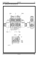


Table Of Contents
- Technical Systems Hydraulic System UNIWRAP
- Contents
- 1 Hydraulic circuit diagram
- 1.1 Hydraulic circuit diagram up to serial no.: 72600130
- 1.2 Hydraulic circuit diagram from machine no.: 72600131, with tipping cradle service shut-off valve (631)
- 1.3 Hydraulic circuit diagram from machine no.: 72600531, with film clamping cutters flow divider (769)
- 1.4 Hydraulic circuit diagram from serial no.: 72601047, with valve combination (630, 706, 769), without 3-stage restrictor (645)
- 1.5 Hydraulic circuit diagram from serial no.: 72601047, with valve combination (630, 706, 769), with 3-stage restrictor (645)
- 2 Pre-conditions for use
- 3 Valve block
- 4 Individual components
- 4.1 Input pressure balance (763)
- 4.2 Circulation shut-off valve (Y77-2)
- 4.3 Wrapping arm control unit (Y133)
- 4.4 Tipping cradle control unit (Y135 / Y136)
- 4.5 Wrapping table control unit (Y137 / Y138)
- 4.6 Clamping cutters control unit (Y139 / Y140)
- 4.7 Flow controller (630)
- 4.8 Pressure relief valve (706)
- 4.9 Wrapping arm motor (234)
- 4.10 Wrapping table motor (235)
- 4.11 Tipping cradle service shut-off valve (631)
- 4.12 Film clamping cutters hydraulic cylinder (374)
- 4.13 Film clamping cutters flow divider (769)
- 4.14 Wrapping arm motor valve block (4)
- 4.15 3-stage restrictor
- 4.16 Valve combination (7)
- 4.17 Manifold (8)
- 0293 522.0

Hydraulic System UNIWRAP TIC
52 UNI-h-Kap4 11/04
Description of function:
No volume flow flowing Due to the two pressure springs located at the face end, spool (2) is
positioned so (see figure) that ports P and A are shut off.
Oil supply is available, but
control unit is not yet
actuated
The volume flow enters the control unit via channel P and flows through
orifice plate (3a) to spool (1).
Since the spool stops the flow, pressure is built up which acts on the
right-hand face end of the 2-way flow controller (3) and via connection
(3b) also in the spring space.
This compensates the pressure at the 2-way flow controller (3) which is
pushed to the right-hand stop by the pressure spring.
Control unit is actuated The speed of the hydraulic motor which drives the wrapping arm depends
on the amount of volume flow.
The higher the volume flow, the higher the motor speed. When the input
volume flow is constant, the hydraulic motor speed will be constant as
well.
When the wrapping arm starts, its speed is to be continuously increased
from 0 to 28 ... 30 rpm. To realise this start-up behaviour, the volume flow
to the hydraulic motor must be continuously increased.
The UNIWRAP electronics module actuates the solenoid coil (Y133) and
continuously increases its force which moves the spool (1) against the
pressure spring to the left.
This opens the connection from P to A continuously, thus constantly
increasing the volume flow and consequently the hydraulic motor speed.
When the solenoid coil (Y133) has moved the spool (1) fully to the left
against the pressure spring, the spool gap has reached its maximum
opening position.
In this position, the 2-way flow controller (767) regulates the volume flow
to approx. 20 l/min on the SAM wrapping arm motor or approx. 31 l/min
on the Danfoss wrapping arm motor, independently from the load.
This keeps the hydraulic motor speed constant.