
User Manual
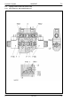

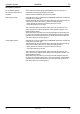


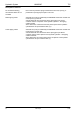
Table Of Contents
- Technical Systems Hydraulic System UNIWRAP
- Contents
- 1 Hydraulic circuit diagram
- 1.1 Hydraulic circuit diagram up to serial no.: 72600130
- 1.2 Hydraulic circuit diagram from machine no.: 72600131, with tipping cradle service shut-off valve (631)
- 1.3 Hydraulic circuit diagram from machine no.: 72600531, with film clamping cutters flow divider (769)
- 1.4 Hydraulic circuit diagram from serial no.: 72601047, with valve combination (630, 706, 769), without 3-stage restrictor (645)
- 1.5 Hydraulic circuit diagram from serial no.: 72601047, with valve combination (630, 706, 769), with 3-stage restrictor (645)
- 2 Pre-conditions for use
- 3 Valve block
- 4 Individual components
- 4.1 Input pressure balance (763)
- 4.2 Circulation shut-off valve (Y77-2)
- 4.3 Wrapping arm control unit (Y133)
- 4.4 Tipping cradle control unit (Y135 / Y136)
- 4.5 Wrapping table control unit (Y137 / Y138)
- 4.6 Clamping cutters control unit (Y139 / Y140)
- 4.7 Flow controller (630)
- 4.8 Pressure relief valve (706)
- 4.9 Wrapping arm motor (234)
- 4.10 Wrapping table motor (235)
- 4.11 Tipping cradle service shut-off valve (631)
- 4.12 Film clamping cutters hydraulic cylinder (374)
- 4.13 Film clamping cutters flow divider (769)
- 4.14 Wrapping arm motor valve block (4)
- 4.15 3-stage restrictor
- 4.16 Valve combination (7)
- 4.17 Manifold (8)
- 0293 522.0

TIC UNIWRAP Hydraulic System
11/04 UNI-h-Kap4 51
Key to diagram:
P Channel pump
Volume flow input from the baler. Channel P continues through
each downstream control unit and is connected with the spool
in each case.
T Return line (tank)
The channel T continues through each of the downstream
control units and is connected with the spool in each case.
LS The LS channel is connected to each of the downstream
control units.
When the wrapping arm rotates, the load pressure acts here.
This pressure signal ends in the input pressure balance.
A Port
The wrapping arm hydraulic motor is connected here.
B Port
The connection is closed.
1 Spool
Actuated by solenoid valve (6).
2 Bore
In the spool, senses the load pressure in port A. Is connected
with the LS channel which ends in the input pressure balance.
3 2-way flow controller
It limits the max. volume flow to the wrapping arm motor to
20 l/min, resulting in a wrapping arm speed of 28 ... 30 l/min.
3a Orifice plate
3b Connection
Is a spiral groove which directs the load pressure from
port A (wrapping arm hydraulic motor) into the spring
space.
4 Spring support
This allows changing the spring force.
767 Wrapping arm motor flow controller
768-2 LS signal shuttle valve
Y133 Solenoid valve
- Is a proportional solenoid valve and actuates spool (1).
- Is actuated by the UNIWRAP electronics module.