
User Manual
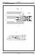
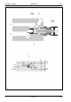
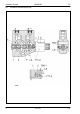


Table Of Contents
- Technical Systems Hydraulic System UNIWRAP
- Contents
- 1 Hydraulic circuit diagram
- 1.1 Hydraulic circuit diagram up to serial no.: 72600130
- 1.2 Hydraulic circuit diagram from machine no.: 72600131, with tipping cradle service shut-off valve (631)
- 1.3 Hydraulic circuit diagram from machine no.: 72600531, with film clamping cutters flow divider (769)
- 1.4 Hydraulic circuit diagram from serial no.: 72601047, with valve combination (630, 706, 769), without 3-stage restrictor (645)
- 1.5 Hydraulic circuit diagram from serial no.: 72601047, with valve combination (630, 706, 769), with 3-stage restrictor (645)
- 2 Pre-conditions for use
- 3 Valve block
- 4 Individual components
- 4.1 Input pressure balance (763)
- 4.2 Circulation shut-off valve (Y77-2)
- 4.3 Wrapping arm control unit (Y133)
- 4.4 Tipping cradle control unit (Y135 / Y136)
- 4.5 Wrapping table control unit (Y137 / Y138)
- 4.6 Clamping cutters control unit (Y139 / Y140)
- 4.7 Flow controller (630)
- 4.8 Pressure relief valve (706)
- 4.9 Wrapping arm motor (234)
- 4.10 Wrapping table motor (235)
- 4.11 Tipping cradle service shut-off valve (631)
- 4.12 Film clamping cutters hydraulic cylinder (374)
- 4.13 Film clamping cutters flow divider (769)
- 4.14 Wrapping arm motor valve block (4)
- 4.15 3-stage restrictor
- 4.16 Valve combination (7)
- 4.17 Manifold (8)
- 0293 522.0

Hydraulic System UNIWRAP TIC
48 UNI-h-Kap4 11/04
Description of function:
The circulation shut-off valve solenoid coil (Y77-2) is actuated whenever a
hydraulic function is to be carried out on the baler (e.g. open tailgate, raise
pick-up ...).
No volume flow flowing
Due to the two pressure springs located at the face end, spool (2) is
positioned so that (see figure):
- channel P is shut off at the spool
- ports A and B are connected with the tank
- bore (2) is connected with the tank.
Hydraulic requirement from
the baler
The UNIWRAP electronics module actuates circulation shut-off valve
solenoid coil (Y77-2). Solenoid coil (Y77-2) moves spool (1) to the left-
hand stop, thus opening the connection from P to A. Since port A is
closed, pressure is built up which then is applied in the LS channel via
bore (2) and LS signal shuttle valve (768-1). This pressure signal is
directed to the upstream input pressure balance (763) via the LS
channel.The pressure balance (763) switches over and shuts off the
connection from P to T which had been open so far. The volume flow is
now available to the baler.