
User Manual
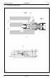
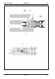
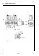


Table Of Contents
- Technical Systems Hydraulic System UNIWRAP
- Contents
- 1 Hydraulic circuit diagram
- 1.1 Hydraulic circuit diagram up to serial no.: 72600130
- 1.2 Hydraulic circuit diagram from machine no.: 72600131, with tipping cradle service shut-off valve (631)
- 1.3 Hydraulic circuit diagram from machine no.: 72600531, with film clamping cutters flow divider (769)
- 1.4 Hydraulic circuit diagram from serial no.: 72601047, with valve combination (630, 706, 769), without 3-stage restrictor (645)
- 1.5 Hydraulic circuit diagram from serial no.: 72601047, with valve combination (630, 706, 769), with 3-stage restrictor (645)
- 2 Pre-conditions for use
- 3 Valve block
- 4 Individual components
- 4.1 Input pressure balance (763)
- 4.2 Circulation shut-off valve (Y77-2)
- 4.3 Wrapping arm control unit (Y133)
- 4.4 Tipping cradle control unit (Y135 / Y136)
- 4.5 Wrapping table control unit (Y137 / Y138)
- 4.6 Clamping cutters control unit (Y139 / Y140)
- 4.7 Flow controller (630)
- 4.8 Pressure relief valve (706)
- 4.9 Wrapping arm motor (234)
- 4.10 Wrapping table motor (235)
- 4.11 Tipping cradle service shut-off valve (631)
- 4.12 Film clamping cutters hydraulic cylinder (374)
- 4.13 Film clamping cutters flow divider (769)
- 4.14 Wrapping arm motor valve block (4)
- 4.15 3-stage restrictor
- 4.16 Valve combination (7)
- 4.17 Manifold (8)
- 0293 522.0

TIC UNIWRAP Hydraulic System
11/04 UNI-h-Kap4 45
Description of function:
No volume flow flowing
The pressure spring pushes the control piston (1) to the left-hand stop.
The connection from P to T is closed.
Volume flow flowing – but
no control unit is actuated
The compression spring pushes the control ram (1) to its left-hand stop.
The connection from P to T is closed.
Volume flow enters the pressure balance via channel P (from the tractor
via the baler) and flows to each of the downstream control units. Since no
control unit is actuated, each spool shuts off the volume flow.
This builds up pressure which acts on the left-hand face end of the
control piston (1) and moves it to the right against the pressure spring.
Now the connection from P to T is opened so that the volume flow flows
back to the baler.
At the same time, a partial volume flow flows via the orifice plate (inside
the control piston) into the spring space of the control piston. The spring
space is pressureless because it is connected with the channel (LS) via
bore (3). This channel is pressureless, too, because no control unit is
actuated.
A pressure difference (∆p) of 9 bar results at the control piston because:
pressure ahead of the control piston = 9 bar
pressure in the spring space = 0 bar
A control unit is actuated,
e.g. the tipping cradle is
raised.
When the corresponding control unit is actuated, volume flow flows via
channel P and the spool into the tipping cradle cylinders. The load
pressure now generated is directed into the control piston spring space
through the LS channel and via bore (3).
This pressure build-up moves the control piston (1) to the left, partly
closing the connection from P to T. This closing is necessary to make
volume flow available for raising the tipping cradle.
However, the control piston is pushed to the left only until the pressure
difference (∆p) of 9 bar is re-established. A part of the volume flow will
continue to flow back to the baler via channel T.
When the tipping cradle cylinders have moved up to their stop, the
pressure rises and is applied in the control piston spring space via the LS
channel and pushes the control piston to the left-hand stop. The pressure
inside channel P actuates the pressure relief valve on the tractor (the
baler and the UNIWRAP are supplied with volume flow from here).