
User Manual
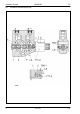


Table Of Contents
- Technical Systems Hydraulic System UNIWRAP
- Contents
- 1 Hydraulic circuit diagram
- 1.1 Hydraulic circuit diagram up to serial no.: 72600130
- 1.2 Hydraulic circuit diagram from machine no.: 72600131, with tipping cradle service shut-off valve (631)
- 1.3 Hydraulic circuit diagram from machine no.: 72600531, with film clamping cutters flow divider (769)
- 1.4 Hydraulic circuit diagram from serial no.: 72601047, with valve combination (630, 706, 769), without 3-stage restrictor (645)
- 1.5 Hydraulic circuit diagram from serial no.: 72601047, with valve combination (630, 706, 769), with 3-stage restrictor (645)
- 2 Pre-conditions for use
- 3 Valve block
- 4 Individual components
- 4.1 Input pressure balance (763)
- 4.2 Circulation shut-off valve (Y77-2)
- 4.3 Wrapping arm control unit (Y133)
- 4.4 Tipping cradle control unit (Y135 / Y136)
- 4.5 Wrapping table control unit (Y137 / Y138)
- 4.6 Clamping cutters control unit (Y139 / Y140)
- 4.7 Flow controller (630)
- 4.8 Pressure relief valve (706)
- 4.9 Wrapping arm motor (234)
- 4.10 Wrapping table motor (235)
- 4.11 Tipping cradle service shut-off valve (631)
- 4.12 Film clamping cutters hydraulic cylinder (374)
- 4.13 Film clamping cutters flow divider (769)
- 4.14 Wrapping arm motor valve block (4)
- 4.15 3-stage restrictor
- 4.16 Valve combination (7)
- 4.17 Manifold (8)
- 0293 522.0

TIC UNIWRAP Hydraulic System
11/04 UNI-h-Kap4 43
Key to diagram:
P Channel pump
Volume flow input from the baler. Channel P continues through
each downstream control unit and is connected with the spool
in each case.
P1 Port. Supply of film cutter control unit
LS The LS channel is connected to each of the downstream
control units. Here the load pressure is applied when a control
unit is actuated.
T Return line (tank).
The channel T continues through each of the downstream
control units and is connected with the spool in each case.
T1 Port.
Return line input from the film cutter control unit.
1 Control ram
The compression spring pushes it to the left-hand stop when no
volume flow is flowing.
3 Bore
It connects the LS channel (load pressure) with the spring
space of the control ram.
634 System screw (option)
763 Input pressure balance