
User Manual
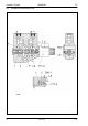


Table Of Contents
- Technical Systems Hydraulic System UNIWRAP
- Contents
- 1 Hydraulic circuit diagram
- 1.1 Hydraulic circuit diagram up to serial no.: 72600130
- 1.2 Hydraulic circuit diagram from machine no.: 72600131, with tipping cradle service shut-off valve (631)
- 1.3 Hydraulic circuit diagram from machine no.: 72600531, with film clamping cutters flow divider (769)
- 1.4 Hydraulic circuit diagram from serial no.: 72601047, with valve combination (630, 706, 769), without 3-stage restrictor (645)
- 1.5 Hydraulic circuit diagram from serial no.: 72601047, with valve combination (630, 706, 769), with 3-stage restrictor (645)
- 2 Pre-conditions for use
- 3 Valve block
- 4 Individual components
- 4.1 Input pressure balance (763)
- 4.2 Circulation shut-off valve (Y77-2)
- 4.3 Wrapping arm control unit (Y133)
- 4.4 Tipping cradle control unit (Y135 / Y136)
- 4.5 Wrapping table control unit (Y137 / Y138)
- 4.6 Clamping cutters control unit (Y139 / Y140)
- 4.7 Flow controller (630)
- 4.8 Pressure relief valve (706)
- 4.9 Wrapping arm motor (234)
- 4.10 Wrapping table motor (235)
- 4.11 Tipping cradle service shut-off valve (631)
- 4.12 Film clamping cutters hydraulic cylinder (374)
- 4.13 Film clamping cutters flow divider (769)
- 4.14 Wrapping arm motor valve block (4)
- 4.15 3-stage restrictor
- 4.16 Valve combination (7)
- 4.17 Manifold (8)
- 0293 522.0

TIC UNIWRAP Hydraulic System
11/04 UNI-h-Kap4 41
4
Individual
components
4.1 Input pressure balance (763) ..........................................................42
4.2 Circulation shut-off valve (Y77-2)....................................................46
4.3 Wrapping arm control unit (Y133) ...................................................50
4.4 Tipping cradle control unit (Y135 / Y136)........................................54
4.4.1 Up to serial no.: with lock-up valve unit ...............................54
4.4.2 From serial no.: without lock-up valve unit ..........................58
4.5 Wrapping table control unit (Y137 / Y138) ......................................62
4.6. Clamping cutters control unit (Y139 / Y140) ...................................66
4.7 Flow controller (630)........................................................................70
4.8 Pressure relief valve (706) ..............................................................74
4.9 Wrapping arm motor (234) ..............................................................76
4.10 Wrapping table motor (235).............................................................78
4.11 Tipping cradle service shut-off valve (631) .....................................80
4.12 Film clamping cutters hydraulic cylinder (374)................................82
4.13 Film clamping cutters flow divider (769)..........................................84
4.14 Wrapping arm motor valve block (4) ...............................................90
4.15 3-stage restrictor .............................................................................92
4.16 Valve combination (7)......................................................................94
4.17 Manifold (8) .....................................................................................96