
User Manual


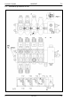

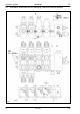

Table Of Contents
- Technical Systems Hydraulic System UNIWRAP
- Contents
- 1 Hydraulic circuit diagram
- 1.1 Hydraulic circuit diagram up to serial no.: 72600130
- 1.2 Hydraulic circuit diagram from machine no.: 72600131, with tipping cradle service shut-off valve (631)
- 1.3 Hydraulic circuit diagram from machine no.: 72600531, with film clamping cutters flow divider (769)
- 1.4 Hydraulic circuit diagram from serial no.: 72601047, with valve combination (630, 706, 769), without 3-stage restrictor (645)
- 1.5 Hydraulic circuit diagram from serial no.: 72601047, with valve combination (630, 706, 769), with 3-stage restrictor (645)
- 2 Pre-conditions for use
- 3 Valve block
- 4 Individual components
- 4.1 Input pressure balance (763)
- 4.2 Circulation shut-off valve (Y77-2)
- 4.3 Wrapping arm control unit (Y133)
- 4.4 Tipping cradle control unit (Y135 / Y136)
- 4.5 Wrapping table control unit (Y137 / Y138)
- 4.6 Clamping cutters control unit (Y139 / Y140)
- 4.7 Flow controller (630)
- 4.8 Pressure relief valve (706)
- 4.9 Wrapping arm motor (234)
- 4.10 Wrapping table motor (235)
- 4.11 Tipping cradle service shut-off valve (631)
- 4.12 Film clamping cutters hydraulic cylinder (374)
- 4.13 Film clamping cutters flow divider (769)
- 4.14 Wrapping arm motor valve block (4)
- 4.15 3-stage restrictor
- 4.16 Valve combination (7)
- 4.17 Manifold (8)
- 0293 522.0

TIC UNIWRAP Hydraulic System
11/04 UNI-h-Kap3 35
Key to diagram:
F Screw plug
Access to flow controller.
Note: Screw plug F must not protrude.
P Pump (supply line)
T Return line (tank)
3a Intermediate plate
763 Input pressure balance
767 Wrapping arm motor flow controller
768 LS signal shuttle valves
Y77 Master valve solenoid valve
Y133 Wrapping arm motor forward solenoid valve
Y135 Lower tipping cradle solenoid valve
Y136 Raise tipping cradle solenoid valve
Y137 Lower wrapping table solenoid valve
Y138 Raise wrapping table solenoid valve