
User Manual


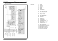

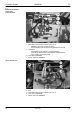
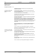
Table Of Contents
- Technical Systems Hydraulic System UNIWRAP
- Contents
- 1 Hydraulic circuit diagram
- 1.1 Hydraulic circuit diagram up to serial no.: 72600130
- 1.2 Hydraulic circuit diagram from machine no.: 72600131, with tipping cradle service shut-off valve (631)
- 1.3 Hydraulic circuit diagram from machine no.: 72600531, with film clamping cutters flow divider (769)
- 1.4 Hydraulic circuit diagram from serial no.: 72601047, with valve combination (630, 706, 769), without 3-stage restrictor (645)
- 1.5 Hydraulic circuit diagram from serial no.: 72601047, with valve combination (630, 706, 769), with 3-stage restrictor (645)
- 2 Pre-conditions for use
- 3 Valve block
- 4 Individual components
- 4.1 Input pressure balance (763)
- 4.2 Circulation shut-off valve (Y77-2)
- 4.3 Wrapping arm control unit (Y133)
- 4.4 Tipping cradle control unit (Y135 / Y136)
- 4.5 Wrapping table control unit (Y137 / Y138)
- 4.6 Clamping cutters control unit (Y139 / Y140)
- 4.7 Flow controller (630)
- 4.8 Pressure relief valve (706)
- 4.9 Wrapping arm motor (234)
- 4.10 Wrapping table motor (235)
- 4.11 Tipping cradle service shut-off valve (631)
- 4.12 Film clamping cutters hydraulic cylinder (374)
- 4.13 Film clamping cutters flow divider (769)
- 4.14 Wrapping arm motor valve block (4)
- 4.15 3-stage restrictor
- 4.16 Valve combination (7)
- 4.17 Manifold (8)
- 0293 522.0

Hydraulic System UNIWRAP TIC
30 UNI-h-Kap1 11/04
Description of function: 2/2
Connection to tractors with
load-sensing system and a
Power Beyond port
The quick release coupling 1 is connected directly to the pump via the
Power Beyond port P.
The quick release coupling 2 is connected to port T (pressureless return
line) of the tractor.
Here the LS connection (LS, working hydraulics signal) is connected with
the LS signal port of the tractor (the kit is available from the spare parts
department).
The system screw 634 is turned in up to the stop so that the input
pressure balance 763 is blocked.
The tractor's hydraulic pump regulates as a function of the attachment's
load signal.
Test points/characteristics When no function is active on the attachment, the attachment must not
load the tractor hydraulically.
(The tractor engine speed must not be reduced).
The allowed temperature of the tractor's hydraulic system must not be
exceeded; see also the Operator's Manual of the tractor.
Connection to tractors with
load-sensing system without
a Power Beyond port
The quick release coupling 1 is connected to a control unit port of the
tractor with adjustable oil flow.
This control unit provides oil supply for the attachment and is adjusted to
a constant volume flow of Q
max
= 35 to 50 l/min.
The system screw 634 is turned out up to the stop so that the input
pressure balance 763 is operative.
The quick release coupling 2 is in general connected to the pressureless
return line T of the tractor.
If a pressureless return line is not allowed in continuous operation (e.g.
because lubrication of the tractor gearbox is not guaranteed), a double-
acting control unit can be used for supplying oil to the attachment.
In this case, the quick release coupling 1 is connected to port A (feed) and
quick release coupling 2 to port B (return) of the corresponding tractor
control valve.
Adjust the volume flow to Q
max
= 35 to 50 l/min; please refer also to the
tractor's Operating Manual (e.g. "Continuous operation of hydraulic
motors").
The LS connection (LS, working hydraulics signal) is not used here.
If the tractor is not provided with a flow-adjustable control unit, the volume
flow must not exceed 35 to 50 l/min.