
User Manual


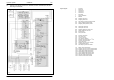
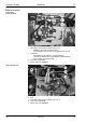
Table Of Contents
- Technical Systems Hydraulic System UNIWRAP
- Contents
- 1 Hydraulic circuit diagram
- 1.1 Hydraulic circuit diagram up to serial no.: 72600130
- 1.2 Hydraulic circuit diagram from machine no.: 72600131, with tipping cradle service shut-off valve (631)
- 1.3 Hydraulic circuit diagram from machine no.: 72600531, with film clamping cutters flow divider (769)
- 1.4 Hydraulic circuit diagram from serial no.: 72601047, with valve combination (630, 706, 769), without 3-stage restrictor (645)
- 1.5 Hydraulic circuit diagram from serial no.: 72601047, with valve combination (630, 706, 769), with 3-stage restrictor (645)
- 2 Pre-conditions for use
- 3 Valve block
- 4 Individual components
- 4.1 Input pressure balance (763)
- 4.2 Circulation shut-off valve (Y77-2)
- 4.3 Wrapping arm control unit (Y133)
- 4.4 Tipping cradle control unit (Y135 / Y136)
- 4.5 Wrapping table control unit (Y137 / Y138)
- 4.6 Clamping cutters control unit (Y139 / Y140)
- 4.7 Flow controller (630)
- 4.8 Pressure relief valve (706)
- 4.9 Wrapping arm motor (234)
- 4.10 Wrapping table motor (235)
- 4.11 Tipping cradle service shut-off valve (631)
- 4.12 Film clamping cutters hydraulic cylinder (374)
- 4.13 Film clamping cutters flow divider (769)
- 4.14 Wrapping arm motor valve block (4)
- 4.15 3-stage restrictor
- 4.16 Valve combination (7)
- 4.17 Manifold (8)
- 0293 522.0

Hydraulic System UNIWRAP TIC
26 UNI-h-Kap1 11/04
Description of function:
Wrapping arm forward
solenoid valve (Y133)
The solenoid valve controls the wrapping arm hydraulic motor.
A wrapping arm motor flow controller (767) is provided in the volume flow
input and keeps the volume flow constant.
When the control unit is activated, this volume flow is pumped to the
hydraulic motor (234) which drives the wrapping arm with 28 … 30 rpm
max. The flow controller may be accessed via the screw plug at the
bottom of the control unit.
The rotational speed of the wrapping arm of 27 rpm ensures that the
wrapping process is shorter than the time required for producing the bale.
Wrapping arm reverse
solenoid valve (Y134)
The solenoid valve changes the direction of oil flow to the wrapping arm
motor (234) and consequently its sense of rotation.
Lower tipping cradle
solenoid valve (Y135)
The solenoid valve lowers the tipping cradle.
Raise tipping cradle
solenoid valve (Y136)
The solenoid valve raises the tipping cradle. The lock-up valve unit (734)
avoids lowering of the raised tipping cradle.
Lower wrapping table
solenoid valve (Y137)
The solenoid valve lowers the wrapping table. The lock-up valve unit
(734) in the cylinder line avoids lowering of the loaded wrapping table.
Raise wrapping table
solenoid valve (Y138)
The solenoid valve raises the wrapping table.
Open film cutters solenoid
valve (Y139)
The solenoid valve opens both film cutters.
The wrapping table raise solenoid coil (Y138) is actuated simultaneously
with solenoid coils (Y139). This is necessary in order to build up pressure
in the LS line to make the input pressure balance (763) close.
Close film cutters solenoid
valve (Y140)
The solenoid valve closes both film cutters.
The wrapping table raise solenoid coil (Y138) is actuated simultaneously
with solenoid coils (Y139). This is necessary in order to build up pressure
in the LS line to make the input pressure balance (763) close.
3-stage restrictor (645) To enable raising and lowering the wrapping table at different speeds, the
respective speed may be preselected using the 3-stage restrictor, see
chapter 4-15.