
User Manual


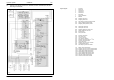

Table Of Contents
- Technical Systems Hydraulic System UNIWRAP
- Contents
- 1 Hydraulic circuit diagram
- 1.1 Hydraulic circuit diagram up to serial no.: 72600130
- 1.2 Hydraulic circuit diagram from machine no.: 72600131, with tipping cradle service shut-off valve (631)
- 1.3 Hydraulic circuit diagram from machine no.: 72600531, with film clamping cutters flow divider (769)
- 1.4 Hydraulic circuit diagram from serial no.: 72601047, with valve combination (630, 706, 769), without 3-stage restrictor (645)
- 1.5 Hydraulic circuit diagram from serial no.: 72601047, with valve combination (630, 706, 769), with 3-stage restrictor (645)
- 2 Pre-conditions for use
- 3 Valve block
- 4 Individual components
- 4.1 Input pressure balance (763)
- 4.2 Circulation shut-off valve (Y77-2)
- 4.3 Wrapping arm control unit (Y133)
- 4.4 Tipping cradle control unit (Y135 / Y136)
- 4.5 Wrapping table control unit (Y137 / Y138)
- 4.6 Clamping cutters control unit (Y139 / Y140)
- 4.7 Flow controller (630)
- 4.8 Pressure relief valve (706)
- 4.9 Wrapping arm motor (234)
- 4.10 Wrapping table motor (235)
- 4.11 Tipping cradle service shut-off valve (631)
- 4.12 Film clamping cutters hydraulic cylinder (374)
- 4.13 Film clamping cutters flow divider (769)
- 4.14 Wrapping arm motor valve block (4)
- 4.15 3-stage restrictor
- 4.16 Valve combination (7)
- 4.17 Manifold (8)
- 0293 522.0

TIC UNIWRAP Hydraulic System
11/04 UNI-h-Kap1 25
Description of function:
Orifice plate (406)
Ø 0.8 mm
The orifice plate (406) Ø 0.8 mm avoids pressure build-up and
consequently uncontrolled movements of the wrapping arm motor (234).
Wrapping table flow control
valve (630)
The wrapping table flow control valve supplies the hydraulic motor (235)
via output (A).
This volume flow can be adjusted and changes the wrapping table motor /
wrapping arm motor speed ratio and consequently the film layer overlaps.
Tipping cradle shut-off valve
(631)
During service work, the tipping cradle shut-off valve shuts off the oil flow
from the hydraulic cylinders 375.
Pressure relief valve (706) The pressure relief valve limits the pressure to 70 bar when lowering the
tipping cradle hydraulic cylinders.
Non-return valve (732-3) The non-return valve avoids faulty functions of the film clamping cutters
by building up pressure in the T line.
Input pressure balance
(763)
The input pressure balance keeps the connection from P to T open when
no control unit is actuated in valve block 3.
It is closed by LS pressure. The LS pressure is built up when the master
valve (Y77-2) or a control unit in valve block 3 is actuated.
Pressure relief valve (764) The pressure relief valve limits the oil pressure to the wrapping arm motor
(234) and the wrapping table motor (drive) connected in series to
115
+10
bar.
Pressure relief valve (765) The pressure relief valve limits the oil pressure of the wrapping arm motor
(234) when decelerating.
Lower brake valve (766) The non-return valves 732-1/ 732-2 and the lower brake valve (766)
decelerate the wrapping arm motor (234) hydraulically on both sides if the
wrapping arm forward solenoid valve (Y133) is not energized.
Wrapping arm motor flow
controller (767)
The flow controller keeps the volume flow to the wrapping arm motor
(234) constant.
Maximum wrapping speed (approx. 20 l/min.) with SAM wrapping arm
motor.
Maximum wrapping speed (approx. 31 l/min.) with Danfoss wrapping arm
motor.
LS signal shuttle valves
(768)
When operating the control valves in parallel mode, the shuttle valves
allow sending the highest load pressure to the input pressure balance
(763) in each case.
Film clamping cutters flow
divider (769)
The flow divider divides the oil flows for opening and closing the film
clamping cutters.
Master valve solenoid valve
(Y77)
The master valve solenoid valve is actuated automatically when a
hydraulic function is to be carried out on the baler. Now the pump flow is
directed into the LS line so that the pressure that builds up closes the
pressure balance (763).