
User Manual


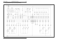
Table Of Contents
- Technical Systems Electric System LEXION 570 – 520 Montana
- Layout of electric circuit diagrams
- Contents
- Central terminal compartment
- Pin assignment in modules
- Module A6 - Automatic air conditioner
- Module A7 - Cab fan speed controller
- Module A8 - AUTOCONTOUR (CAC)
- Module A9 – AUTOPILOT (ATP)
- Module A10 - Fieldwork computer (BIF/CAB)
- Module A12 - Speed monitor (DZW)
- Module A13 - Performance monitor (DKG)
- Module A15 - Electronic engine control module CATERPILLAR (CAT)
- Module A15 - Electronic engine control module DAIMLER-CHRYSLER (DC)
- Module A17 - Engine adaptation module ADM DAIMLER-CHRYSLER (DC)
- Module A16 – Reel controller
- Module A21 - Yield meter
- Module A25 - Sieve adjustment
- Module A27 - VARIO
- Module A28 - Uni-spreader (VGS)
- Module A30 - Terminal
- Module A33 - Sidefinder
- Module A34 - Grain tank
- Module A35 - Montana 570-520 control unit - with external MONTANA control unit (up to serial no. 582 00051, 581 00026; 580 00028)
- Module A36 - Montana 570-520 gearshift module - with external MONTANA control unit (up to serial no. 582 00051, 581 00026; 580 00028)
- Module A37 – Electro-hydraulic gearshift (EHS) - 3-speed manual gearbox
- Module A37 – Electro-hydraulic gearshift (EHS) - 2-speed manual gearbox
- Module A38 – Rotor (RIO)
- Module A42 – MONTANA GEN II module - with integrated MONTANA control unit from serial no. 582 00052, 581 00027 and 580 00029)
- Module A45 - Ground drive hydraulic motor brake restrictor (HBM)
- Module A46 – Deflector adjustment (RIO)
- Module A49 – Ground drive (EFA)
- Module A51 – Radial spreader
- Module A65 - GPS pilot terminal
- Module A66 - GPS pilot module (GPB)
- Circuit diagram 1a - 50a
- 01a - Main power supply, diesel engine electric starting motor
- 01s - Main power supply, diesel engine electric starting motor - Montana 570-520
- 02a - Starting the diesel engine, diesel engine electric starting motor - CAT C12, C10, C9, 3126B
- 02b - Starting the diesel engine, diesel engine electric starting motor- DC 502 LA
- 02s - Starting the diesel engine, diesel engine speed adjustment - CAT C12, C10, C9, 3126B, Montana 570-520 - with external MONTANA control unit (up to serial no. 582 00051, 581 00026; 580 00028)
- 02t - Starting the diesel engine, diesel engine speed adjustment
- 03a - Diesel engine cut-off system
- 04a - Road travel activation, master valve
- 04s - Road travel activation, working hydraulics master valve, Montana 570-520 - with external MONTANA control unit (up to serial no. 582 00051, 581 00026; 580 00028)
- 04t - Road travel activation, working hydraulics master valve, Montana 570-520 - with integrated MONTANA control unit (from serial no. 581 00027 to 581 00037)
- 05a - Terminal, keyboard, rotary switch, printer
- 06a - CAN bus, module power supply, for diesel engine CATERPILLAR - C12, C10, C9, 3126B
- 06b - CAN bus, module power supply, for diesel engine Daimler - Chrysler DC 502 LA
- 06s - CAN bus, module power supply, Montana 570-520 - with external MONTANA control unit (up to serial no. 582 00051, 581 00026; 580 00028)
- 06t - CAN bus, module power supply, Montana 570-520 - with integrated MONTANA control unit (from serial no. 581 00027 to 581 00037)
- 07a - Threshing mechanism circuit
- 08a - Concave adjustment / Threshing drum variable-speed drive
- 09a - Rotor flap adjustment / Rotor variable-speed drive
- 10a - Fan variable-speed drive
- 11a - Sieve adjustment
- 12a - Deflector adjustment
- 13a - Straw and chaff spreader, uni-spreader - LEXION 580
- 13b - Straw and chaff spreader, radial spreader
- 14a - Swinging the grain tank unloading tube
- 15a - Grain tank unloading / Grain tank unloading aid
- 16a - Rape cutting knife circuit
- 17a - Front attachment drive, reverser drive, front attachment quick stop
- 17s - Front attachment drive, reverser drive, front attachment quick stop, Montana 570-520 - with external MONTANA control unit (up to serial no. 582 00051, 581 00026; 580 00028)
- 18a - Front attachment variable-speed drive
- 19a - Straw chopper
- 19b - Straw chopper, radial spreader without chaff spreader
- 19c - Straw chopper, radial spreader with chaff spreader
- 20a - Front attachment raise/lower, cross levelling
- 20s - Raise/lower front attachment, cross levelling - Montana 570-520
- 21a - Reel adjustment - Standard cutterbar
- 21b - Reel adjustment - VARIO cutterbar
- 21c - Reel adjustment - Folding cutterbar
- 21d - Folding the maize picker, snapping plate adjustment, down maize augers
- 22a - Reel variable-speed drive
- 23a - Cutting table adjustment (Vario), folding the cutterbar
- 24a - AUTOCONTOUR (CAC)
- 25a - Speed monitor
- 26a - Machine monitor
- 26s - Machine monitor, Montana 570-520 - with external MONTANA control unit (up to serial no. 582 00051, 581 00026; 580 00028)
- 26t - Machine monitor, Montana 570-520 - with integrated MONTANA control unit (from serial no. 581 00027 to 581 00037)
- 27a - Yield meter / Grainmeter
- 28a - AUTOPILOT – Laser system
- 28b - AUTOPILOT – Feeler system
- 28c - AUTOPILOT – GPS-controlled steering
- 29a - Performance monitor
- 30a - Open / close grain tank (electric), grain tank full signal, warning beacon
- 30b - Open / close grain tank (hydraulic), grain tank full signal, warning beacon
- 31a - Front attachment dampening
- 32a - All-wheel drive, fuel tank
- 32b - All-wheel drive - overdrive, fuel tank
- 33a - Cutterbar spring lock
- 36a - Indicator system (Europe)
- 36b - Indicator system (USA)
- 37a - Windscreen wiper, windscreen washer
- 38a - Compressor-type air conditioner
- 38b - Automatic air conditioner
- 39a - Cab comfort equipment – operator's seat
- 40a - Additional sockets, fuse tester
- 41s - Axle control system, front attachment control system, Montana 570-520 - with integrated MONTANA control unit (up to serial no. 582 00051, 581 00026; 580 00028)
- 41t - Axle control system and front attachment contr
- 42a - Ground drive and brake control
- 42s - Ground drive and brake control, Montana 570-520 - with external MONTANA control unit (up to serial no. 582 00051, 581 00026; 580 00028)
- 42t - Ground drive and brake control, Montana 570-520 - with integrated MONTANA control unit (from serial no. 581 00027 to 581 00037)
- 44a - Electro-hydraulic gearshift - 3-speed manual gearbox
- 45a - Main lighting circuit, taillight, position light
- 46a - Dipped headlights, full beam, dipped headlights changeover switch
- 47a - Work lights I
- 48a - Work lights II
- 49a - Sieve, grain tank and returns lighting, reversing horn, brake light
- 50a - Instrument lighting, broadcast receiver, mirror adjustment
- Component grid
- Index
- 0293 676.0

TIC LEXION Montana 570-520 Electric System
03/05 Lex-e-41s 41s-3
Description of function:
1/5
Axle control system and
front attachment control
system
The system identifies the machine position using the inclination sensors
B126-1 / B126-2 which transmit their values to the Montana module (A35)
via an internal CAN bus. The solenoid coils (Y114, Y115, Y116, Y117) are
actuated by the Montana module (A35) so that the machine is always in a
vertical position by means of front axle movements. If the control system
speed is not sufficient, the Montana module (A35) additionally actuates an
oil quantity increase solenoid coil (Y118) in connection with the working
hydraulics master valve (Y77) via the gear pre-selection module (A36) -
circuit diagram 4s.
The position of the front attachment is adapted by rotating the front
attachment frame (Y112, Y113) and by changing the cutting angle (Y110,
Y111). This front attachment control system works independently of the
AUTOCONTOUR system.
The Montana module (A35) receives the necessary feedback about the
current position of the corresponding function from the respective angle
sensors (B91, B92, B93, B94, B95).
Important! All system calibrations using the Montana terminal (A41)
require that the Montana control unit module A35 receives
the signal from the unactuated parking brake (S93) - Circuit
diagram 42s.
Axle control system
diagnosis via Montana
terminal A41
Call up the diagnosis menu with the menu key, the yellow cutting angle
increase / decrease keys and the Enter key.
- Diagnosis inputs Select the inputs section using the yellow keys and the Enter key.
Diagnose
Inputs
Inclinometer
Outputs
System