
User Manual
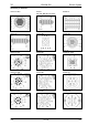


Table Of Contents
- Technical Systems Electric System LEXION 570 – 520 Montana
- Layout of electric circuit diagrams
- Contents
- Central terminal compartment
- Pin assignment in modules
- Module A6 - Automatic air conditioner
- Module A7 - Cab fan speed controller
- Module A8 - AUTOCONTOUR (CAC)
- Module A9 – AUTOPILOT (ATP)
- Module A10 - Fieldwork computer (BIF/CAB)
- Module A12 - Speed monitor (DZW)
- Module A13 - Performance monitor (DKG)
- Module A15 - Electronic engine control module CATERPILLAR (CAT)
- Module A15 - Electronic engine control module DAIMLER-CHRYSLER (DC)
- Module A17 - Engine adaptation module ADM DAIMLER-CHRYSLER (DC)
- Module A16 – Reel controller
- Module A21 - Yield meter
- Module A25 - Sieve adjustment
- Module A27 - VARIO
- Module A28 - Uni-spreader (VGS)
- Module A30 - Terminal
- Module A33 - Sidefinder
- Module A34 - Grain tank
- Module A35 - Montana 570-520 control unit - with external MONTANA control unit (up to serial no. 582 00051, 581 00026; 580 00028)
- Module A36 - Montana 570-520 gearshift module - with external MONTANA control unit (up to serial no. 582 00051, 581 00026; 580 00028)
- Module A37 – Electro-hydraulic gearshift (EHS) - 3-speed manual gearbox
- Module A37 – Electro-hydraulic gearshift (EHS) - 2-speed manual gearbox
- Module A38 – Rotor (RIO)
- Module A42 – MONTANA GEN II module - with integrated MONTANA control unit from serial no. 582 00052, 581 00027 and 580 00029)
- Module A45 - Ground drive hydraulic motor brake restrictor (HBM)
- Module A46 – Deflector adjustment (RIO)
- Module A49 – Ground drive (EFA)
- Module A51 – Radial spreader
- Module A65 - GPS pilot terminal
- Module A66 - GPS pilot module (GPB)
- Circuit diagram 1a - 50a
- 01a - Main power supply, diesel engine electric starting motor
- 01s - Main power supply, diesel engine electric starting motor - Montana 570-520
- 02a - Starting the diesel engine, diesel engine electric starting motor - CAT C12, C10, C9, 3126B
- 02b - Starting the diesel engine, diesel engine electric starting motor- DC 502 LA
- 02s - Starting the diesel engine, diesel engine speed adjustment - CAT C12, C10, C9, 3126B, Montana 570-520 - with external MONTANA control unit (up to serial no. 582 00051, 581 00026; 580 00028)
- 02t - Starting the diesel engine, diesel engine speed adjustment
- 03a - Diesel engine cut-off system
- 04a - Road travel activation, master valve
- 04s - Road travel activation, working hydraulics master valve, Montana 570-520 - with external MONTANA control unit (up to serial no. 582 00051, 581 00026; 580 00028)
- 04t - Road travel activation, working hydraulics master valve, Montana 570-520 - with integrated MONTANA control unit (from serial no. 581 00027 to 581 00037)
- 05a - Terminal, keyboard, rotary switch, printer
- 06a - CAN bus, module power supply, for diesel engine CATERPILLAR - C12, C10, C9, 3126B
- 06b - CAN bus, module power supply, for diesel engine Daimler - Chrysler DC 502 LA
- 06s - CAN bus, module power supply, Montana 570-520 - with external MONTANA control unit (up to serial no. 582 00051, 581 00026; 580 00028)
- 06t - CAN bus, module power supply, Montana 570-520 - with integrated MONTANA control unit (from serial no. 581 00027 to 581 00037)
- 07a - Threshing mechanism circuit
- 08a - Concave adjustment / Threshing drum variable-speed drive
- 09a - Rotor flap adjustment / Rotor variable-speed drive
- 10a - Fan variable-speed drive
- 11a - Sieve adjustment
- 12a - Deflector adjustment
- 13a - Straw and chaff spreader, uni-spreader - LEXION 580
- 13b - Straw and chaff spreader, radial spreader
- 14a - Swinging the grain tank unloading tube
- 15a - Grain tank unloading / Grain tank unloading aid
- 16a - Rape cutting knife circuit
- 17a - Front attachment drive, reverser drive, front attachment quick stop
- 17s - Front attachment drive, reverser drive, front attachment quick stop, Montana 570-520 - with external MONTANA control unit (up to serial no. 582 00051, 581 00026; 580 00028)
- 18a - Front attachment variable-speed drive
- 19a - Straw chopper
- 19b - Straw chopper, radial spreader without chaff spreader
- 19c - Straw chopper, radial spreader with chaff spreader
- 20a - Front attachment raise/lower, cross levelling
- 20s - Raise/lower front attachment, cross levelling - Montana 570-520
- 21a - Reel adjustment - Standard cutterbar
- 21b - Reel adjustment - VARIO cutterbar
- 21c - Reel adjustment - Folding cutterbar
- 21d - Folding the maize picker, snapping plate adjustment, down maize augers
- 22a - Reel variable-speed drive
- 23a - Cutting table adjustment (Vario), folding the cutterbar
- 24a - AUTOCONTOUR (CAC)
- 25a - Speed monitor
- 26a - Machine monitor
- 26s - Machine monitor, Montana 570-520 - with external MONTANA control unit (up to serial no. 582 00051, 581 00026; 580 00028)
- 26t - Machine monitor, Montana 570-520 - with integrated MONTANA control unit (from serial no. 581 00027 to 581 00037)
- 27a - Yield meter / Grainmeter
- 28a - AUTOPILOT – Laser system
- 28b - AUTOPILOT – Feeler system
- 28c - AUTOPILOT – GPS-controlled steering
- 29a - Performance monitor
- 30a - Open / close grain tank (electric), grain tank full signal, warning beacon
- 30b - Open / close grain tank (hydraulic), grain tank full signal, warning beacon
- 31a - Front attachment dampening
- 32a - All-wheel drive, fuel tank
- 32b - All-wheel drive - overdrive, fuel tank
- 33a - Cutterbar spring lock
- 36a - Indicator system (Europe)
- 36b - Indicator system (USA)
- 37a - Windscreen wiper, windscreen washer
- 38a - Compressor-type air conditioner
- 38b - Automatic air conditioner
- 39a - Cab comfort equipment – operator's seat
- 40a - Additional sockets, fuse tester
- 41s - Axle control system, front attachment control system, Montana 570-520 - with integrated MONTANA control unit (up to serial no. 582 00051, 581 00026; 580 00028)
- 41t - Axle control system and front attachment contr
- 42a - Ground drive and brake control
- 42s - Ground drive and brake control, Montana 570-520 - with external MONTANA control unit (up to serial no. 582 00051, 581 00026; 580 00028)
- 42t - Ground drive and brake control, Montana 570-520 - with integrated MONTANA control unit (from serial no. 581 00027 to 581 00037)
- 44a - Electro-hydraulic gearshift - 3-speed manual gearbox
- 45a - Main lighting circuit, taillight, position light
- 46a - Dipped headlights, full beam, dipped headlights changeover switch
- 47a - Work lights I
- 48a - Work lights II
- 49a - Sieve, grain tank and returns lighting, reversing horn, brake light
- 50a - Instrument lighting, broadcast receiver, mirror adjustment
- Component grid
- Index
- 0293 676.0

TIC LEXION Montana 570-520 Electric System
03/05 Lex-e-06s 6s-3
Measured value table:
Item Component Measured value Remark
R14 Resistor
approx. 120 Ω
K56 Remote control relay
15 A
30 A
95±10 Ω
(Pin 86/1 – 85/2)
(Pin 87a/4 – 30/3)
(Pin 87/5 – 30/3)
Key to diagram:
Coordinates
A1 AGROCOM terminal ............................................................2-i-17
A8 AUTOCONTOUR module (CAC).........................................2-i-20
A9 AUTOPILOT module............................................................2-i-20
A10 Fieldwork computer module (BIF/CAB) ...............................2-i-20
A12 Speed monitor module (DZW) .............................................2-i-20
A13 Performance monitor module (DKG) ................................. 4-p-20
A15 Electronic engine control module....................................... 3-p-18
A16 Reel controller module (HAS) ..............................................2-i-20
A21 YIELD METER module (LEM) .............................................2-i-20
A25 Sieve adjustment module.....................................................2-i-20
A27 VARIO module .................................................................... 8-f-20
A28 Uni-spreader module (VGS) ................................................2-i-20
A30 Terminal ............................................................................ 3-g-17
A35 Montana control unit module................................................7-i-18
A38 Rotor RIO module (RIO) .................................................... 4-n-20
A45 Ground drive hydraulic motor brake
restrictor module (HBM).......................................................4-i-20
A40 Axle control system adaptation module ............................. 2-h-17
A41 Montana terminal ................................................................ 3-f-17
A46 Deflector adjustment module (RIO) .................................... 5-t-16
A51 Radial spreader module......................................................5-s-18
B50 L AUTOPILOT laser sensor, left ........................................... 6-e-25
B50 R AUTOPILOT laser sensor, right......................................... 6-e-11
DS Diagnosis plug (63-pin) VIA .................................................3-i-20
XM Caterpillar diagnosis connector............................................4-i-20
K14 Threshing mechanism relay.................................................4-i-20
K49 Road travel main relay .........................................................4-i-20
K52 Power supply relay...............................................................4-i-20
K51 Power supply relay...............................................................4-i-20
K56 Electronic unit plus relay ......................................................4-i-20
R14 CAN bus matching resistor ................................................ 3-q-18
XFL External CAN bus connection
(e.g. flagging box, Agrocom terminal, etc.) ........................ 3-h-17
XGSM External CAN bus connection
(e.g. GSM modem) ............................................................ 3-h-17
XQ Performance monitor connector......................................... 5-p-20
XA Multifunction coupling A connector ..................................... 7-f-20
XB Multifunction coupling B connector ..................................... 7-f-20
XC Multifunction coupling C connector..................................... 7-f-20
XD CAN bus terminal connector (7-pin)................................... 3-g-17
XD-2 CAN bus connector (8-pin) ..................................................4-i-17
XV3 AUTOPILOT variant plug connector ................................... 7-f-20