
User Manual


CLA-VAL
Copyright Cla-Val 2013 Printed in USA Specifications subject to change without notice.
P.O. Box 1325 • Newport Beach, CA 92659-0325 • Phone: 949-722-4800 • Fax: 949-548-5441 • E-mail: claval@cla-val.com • Website cla-val.com
©
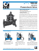
Cla-Val Control Valves operate with maximum efficiency when mounted in horizontal piping with the main valve cover UP, however, other posi-
tions are acceptable. Due to component size and weight of 10 inch and larger valves, installation with cover UP is advisable. We recommend
isolation valves be installed on inlet and outlet for maintenance. Adequate space above and around the valve for service personnel should be
considered essential. A regular maintenance program should be established based on the specific application data. However, we recommend a
thorough inspection be done at least once a year. Consult factory for specific recommendations.
E-100-22 (R-2/2013)
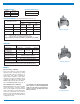
EE
D
E
Inlet
DD
AA
100-22
Flanged
F
A
C
(MAX)
K
J
H
Inlet
Outlet
FF
B
(Diameter)
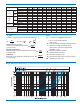
Model 100-22
Dimensions
Valve Size (Inches)
4 6 8 10 12 14 16 18 20 24
A 150 ANSI
13.88 17.75 21.38 26.00 30.00 34.25 35.00 42.12 48.00 48.00
AA 300 ANSI
14.50 18.62 22.38 27.38 31.50 35.75 36.62 43.62 49.62 49.75
B Dia.
9.12 11.50 15.75 20.00 23.62 28.00 28.00 35.44 35.44 35.44
C Max.
11.75 15.25 20.25 23.75 27.25 29.31 34.12 35.00 40.25 40.25
D 150 ANSI
6.94 8.88 10.69 — — — — — — —
DD 300 ANSI
7.25 9.38 11.19 — — — — — — —
E 150 ANSI
5.50 6.75 7.25 — — — — — — —
EE 300 ANSI
5.81 7.25 7.75 — — — — — — —
F 150 ANSI
4.50 5.50 6.75 8.00 9.50 11.00 11.75 15.88 14.56 17.00
FF 300 ANSI
5.00 6.25 7.50 8.75 10.25 — 12.75 15.88 16.06 19.00
H NPT Body Tapping
.50 .75 .75 1 1 1 1 1 1 1
J NPT Cover Center Plug
.50 .75 .75 1 1 1.25 1.25 2 2 2
K NPT Cover Tapping
.50 .75 .75 1 1 1 1 1 1 1
Valve Stem Internal
Thread UNF
1
⁄4-28
1
⁄4-28
3
⁄8-24
3
⁄8-24
3
⁄8-24
3
⁄8-24
3
⁄8-24
1
⁄2-20
1
⁄2-20
1
⁄2-20
Stem Travel
0.8 1.1 1.7 2.3 2.8 3.4 3.4 4.5 4.5 4.5
Approx. Ship Wt. Lbs.
135 230 480 785 1410 2215 2215 2300 3400 3600
Valve Size (mm)
100 150 200 250 300 350 400 450 500 600
A 150 ANSI
353 451 543 660 762 870 889 1070 1219 1219
AA 300 ANSI
368 473 568 695 800 — 930 1108 1260 1263
B Dia.
232 292 400 508 600 711 711 900 900 900
C Max.
298 387 514 603 692 744 867 889 1022 1022
D 150 ANSI
176 226 272 — — — — — — —
DD 300 ANSI
184 238 284 — — — — — — —
E 150 ANSI
140 171 184 — — — — — — —
EE 300 ANSI
148 184 197 — — — — — — —
F 150 ANSI
114 140 171 203 241 279 298 403 370 432
FF 300 ANSI
127 159 191 222 260 — 324 403 408 483
H NPT Body Tapping
.50 .75 .75 1 1 1 1 1 1 1
J NPT Cover Center Plug
.50 .75 .75 1 1 1.25 1.25 2 2 2
K NPT Cover Tapping
.50 .75 .75 1 1 1 1 1 1 1
Valve Stem Internal
Thread UNF
1
⁄4-28
1
⁄4-28
3
⁄8-24
3
⁄8-24
3
⁄8-24
3
⁄8-24
3
⁄8-24
1
⁄2-20
1
⁄2-20
1
⁄2-20
Stem Travel
20 28 43 58 71 86 86 86 114 114
Approx. Ship Wt. Kgs.
61 104 218 356 640 1006 1006 1044 1544 1634