
Manual

For assistance in selecting appropriate valve options or valves manufactured with special design requirements, please contact our Regional Sales Office or Factory.
Model 100-01KO
Functional Data
K =
894d
4
C
2
v
L =
K
12 f
K Factor (Resistance Coefficient)
The Value of K is calculated from the formula:
(U.S. system units)
Equivalent Length of Pipe
Equivalent lengths of pipe (L) are determined from the formula:
(U.S. system units)
Fluid Velocity
Fluid velocity can be calculated from the following formula:
(U.S. system units)
d
V =
.4085 Q
2
d
C
V
Factor
Formulas for computing C Factor, Flow (Q) and Pressure Drop
V
( P):
C
V
=
Q
P
C
V
=
Q
P
C
V
=
Q
P
2
V
Where:
U.S. (gpm) @ 1 psi differential at 60 F water
(l/s) @ 1 bar (14.5 PSIG) differential
or
at 15 C water
inside pipe diameter of Schedule 40 Steel Pipe (inches)
friction factor for clean, new Schedule 40 pipe
(dimensionless) (from Cameron Hydraulic Data,
18th Edition, P 3-119)
Resistance Coefficient (calculated)
Equivalent Length of Pipe (feet)
Flow Rate in U.S. (gpm) or (l/s)
Fluid Velocity (feet per second) or (meters per second)
Pressure Drop in (psi) or (bar)
=
=
=
=
=
=
=
=
=
P
V
Q
L
K
f
d
C
Notes: On Operating Differential
1. For atmospheric discharge, the
maximum inlet pressure cannot
exceed 150 psi.
2. For pressure differentials greater
than 300 psi the maximum flow
velocity should not exceed 18 ft/sec.
3. Flow velocities greater than 25 ft/sec
are not recommended.
4. Recommended minimum flow velocity
is 1 ft/sec.
5. Consult factory for conditions
exceeding these recommendations.
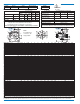
100G-01KO ANTI-CAVITATION VALVE CURVES
100
10
1000
10000
FLOW RATE (gpm)
10
100
PRESSURE DROP (psi)
400
1
300
SOLID LINE IS FULL OPEN FLOW CURVES FOR 18 FT/SEC CONTINUOUS DUTY APPLICATIONS
DASHED LINE IS FULL OPEN FLOW CURVE FOR 25 FT/SEC INTERMITTENT DUTY APPLICATIONS
100000
3"
4"
6"
8"
10"
12"
2"
2 1/2"
1 1/2"
16"
14"
20"
36"
30"
18"
1 1/4"
24"
1"
SELECTION GUIDELINE FOR KO ANTI-CAVITATION VALVES
400
350
300
200
150
100
50
0
010
20 30
40 60
50
70 80
OUTLET PRESSURE (psi)
250
INLET PRESSURE (psi)
Cavitation
Zone
90 100
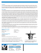
COVER
PIPE PLUG
COVER BEARING
SPRING
STEM NUT
DIAPHRAGM WASHER
DISC RETAINER
BODY
*
SPACER WASHERS
PIPE PLUG
SEAT O-RING
STUD
8" and Larger
*
DIAPHRAGM
*
DISC
*
Repair Parts
PIPE PLUG
HEX NUT
8" and Larger
KO
DISC GUIDE
STEM
(Globe
Shown)
KO
SEAT
Seat Screw
8" and Larger
Cover Bolt
6" and Smaller
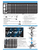
Valve Size
Inches 1
1
⁄4 1
1
⁄2 22
1
⁄2 3468101214161820243036
mm.
32 40 50 65 80 100 150 200 250 300 350 400 450 500 600 750 900
C
V
Factor
Globe
Pattern
Gal./Min. (gpm.)
14 14 25 37 52 90 218 362 602 900 1100 1200 1550 1950 3900 4660 7100
Litres/Sec. (l/s.)
3.4 3.4 6.0 8.9 12.5 21.6 52 87 144 216 264 288 360 469 938 1120 1706
Angle
Pattern
Gal./Min. (gpm.)
15 15 26 39 55 95 232 388 560 790 1075 1175 — — 3775 — —
Litres/Sec. (l/s.)
3.6 3.6 6.2 9.4 13.2 22.8 56 93 134 190 258 282 — — 906 — —
Equivalent
Length of
Pipe
Globe
Pattern
Feet (ft.)
196 196 237 277 416 572 858 1315 1483 2118 1937 3022 3537 4199 4532 6678 6567
Meters (m.)
60 60 72 84 127 174 262 401 452 646 590 921 1078 1280 1381 2035 2002
Angle
Pattern
Feet (ft.)
171 171 219 250 372 514 757 1145 1714 2226 2021 3152 — — 2583 — —
Meters (m.)
52 52 67 76 113 157 231 349 522 678 616 961 — — 787 — —
K Factor
Globe Pattern
30.6 30.6 26.1 24.3 29.3 29.0 25.5 27.7 24.9 27.7 22.8 31.4 30.2 29.5 15.4 30.1 25.1
Angle Pattern
26.7 26.7 24.1 21.8 26.2 26.0 22.5 24.1 28.7 29.1 23.8 32.8 — — 16.4 — —
Liquid Displaced from
Cover Chamber When
Valve Opens
U.S. Gal.
0.2 0.2 .03 .04 .08 .17 .53 1.26 2.5 4.0 6.5 9.6 11 12 29 65 90
Litres
0.8 0.8 .12 .16 .30 .64 2.0 4.8 9.5 15.1 25.6 36.2 41.6 45.4 110 246 340