
Operation Manual
Page 11 of 25
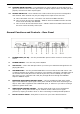
12. CHANNEL GAIN CONTROL – This adjustment is used to adjust an audio signal input
gain for a channel. Never use the gain control to adjust output volume. Set the gain level
properly will ensure a clean output signal.
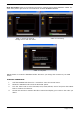
13. SOURCE SELECTOR – These switches are used to select the input source assigned to
each channel. Each channel may only be assigned one input source at a time.
a. CH1 & CH2 both set to PC – the entire unit works as a MIDI controller.
b. CH1 set to PC & CH2 set to DECK B – DECK A works as a MIDI controller and the
mixer works internally with DECK B.
c. CH1 set to PC & CH2 selected to L2/P2 – DECK A works as a MIDI controller and
the mixer works internally with L2/P2.
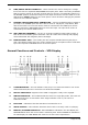
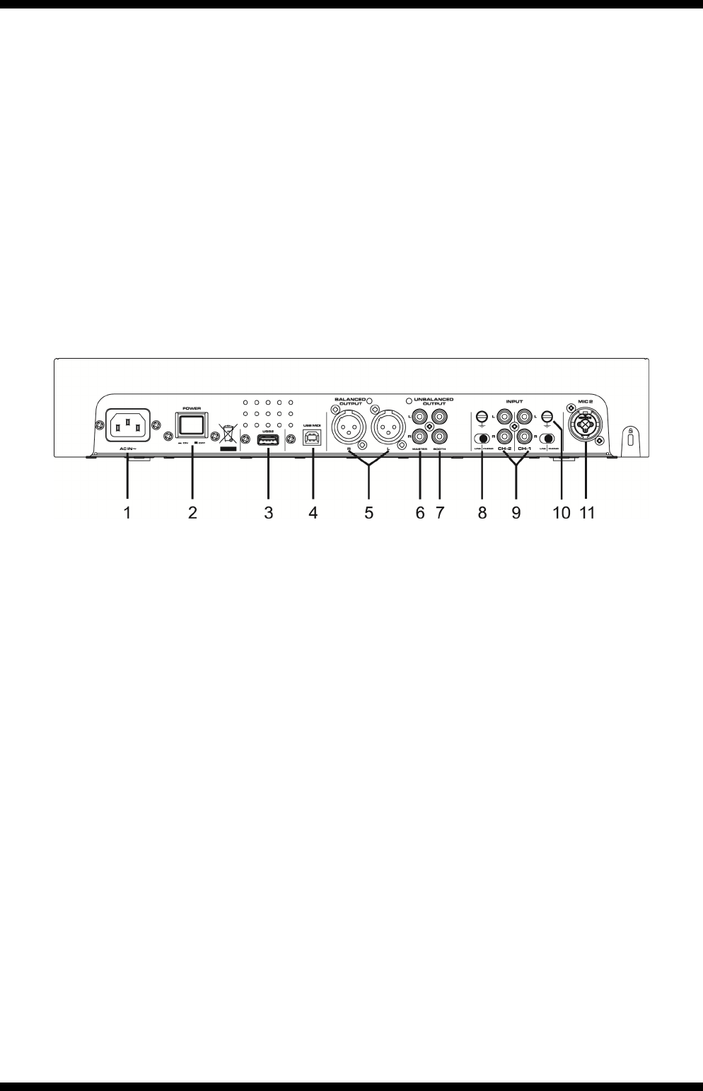
General Functions and Controls – Rear Panel
1. POWER INLET (AC IN) – Use the provided IEC power lead to connect to an AC power
source.
2. POWER SWITCH – Turn the unit power ON/OFF
3. USB 2 PORT – This is the USB port where you insert your USB mass storage device for
playing MP3 files.
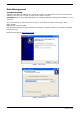
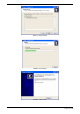
4. USB MIDI PORT – Use the provided USB cable to connect the Citronic MP-X10 to a PC
or Laptop computer by a USB2.0 connection. The computer will detect it straight away as
an external sound card (No need to install any drivers). Once installed you may then
play music on your computer and it will play through MP-X10 through the MASTER
output or BOOTH output.
5. BALANCED XLR MASTER OUTPUT JACKS – L & R 3-pin balanced XLR jacks send a
high current balanced output signal. These jacks should be used when connecting to an
amp or other audio equipment with a balanced input, or whenever you will be running a
signal line greater than 4.5m.
6. UNBALANCED MASTER OUTPUT – The RCA jacks send a low current unbalanced
output signal. These jacks should only be used for shorter cable runs to signal
processors, looping to another mixer or when connecting to small powered speakers.
7. BOOTH OUTPUT JACKS – RCA jacks to connect to your active booth monitors.