Command Reference LINE THERMAL PRINTER MODEL PPU-231II Rev. 1.
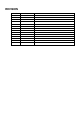
REVISION Rev.No. Rev. 1.00 Rev. 1.01 Date Jun. 10, 2002 Dec. 19, 2002 Comment Newly issued Revised P. 12, P. 78, P. 79, P.
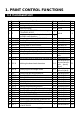
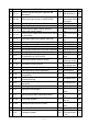
1. PRINT CONTROL FUNCTIONS 1.1 Command List No.
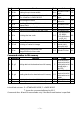
No. Command Function Specifying/Canceling 90°-right-turned characters Mode 32 ESC W Defining the print area in PAGE MODE P* 33 ESC \ 34 ESC a Specifying the relative position S.P.* Aligning the characters S.P. Selecting the Paper Sensor valid for S.P. paper end signal output Selecting the Paper Near-end Sensor valid S.P. for print stop 31 ESC V 35 ESC c3 36 ESC c4 S 37 ESC c5 Enabling/Disabling the panel switches S.P.
No.
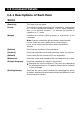
1.2 Command Details 1.2.1 Descriptions of Each Item XXXX [Function] The name of a command. [Code] The string of codes comprising the command is represented by < >H for hexadecimal numbers, < >B for binary numbers, and < > for decimal numbers, [ ] k denotes the number of repetition of “k” times. [Range] Indicates the values (setting range) of argumeuts of the command.
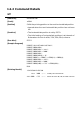
1.2.2 Command Details HT [Function] Horizontal tab [Code] <09>H [Outline] Shifts the printing position to the next horizontal tab position. • Ignored when the next horizontal tab position has not been set. [Caution] • The horizontal tab position is set by ESC D. • The initial setting of horizontal tab positions is at intervals of 8 characters for font A at 9th, 17th, 25th, 33rd, columns.
LF [Function] Printing and paper feed [Code] <0A>H [Outline] Prints data inside the print buffer and feeds paper based on the line feed amount having been set. [Caution] The head of the line becomes the next print starting position.
CR [Function] Back to printing [Code] <0D>H [Outline] 1) When DSW1-5 is OFF: This command is ignored. 2) When DSW1-5 is ON: With data held inside the internal print buffer, printing and line feed are performed. Without data inside the internal print buffer, however, only line feed is performed.
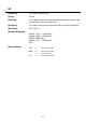
FF (Page Mode) [Function] Printing in PAGE MODE and returning to STANDARD MODE [Code] <0C>H [Outline] Executes a batch printout of the data mapped in the entire print area, and then returns to STANDARD MODE. [Caution] • All mapped data is erased after printout. • The print area set up by ESC W is initialized. • This command does not execute a paper cut. • After this command is executed, the beginning of the line is taken as the start position for the next print.
CAN [Function] Canceling print data in PAGE MODE [Code] <18>H [Outline] Erases all data contained in the currently effective print area in PAGE MODE. [Caution] • This command is only effective when PAGE MODE is selected. • If the previously established print area overlaps the currently effective print area, the overlapped data in the previously established area will be erased.
DLE EOT n [Function] Sending status in real-time [Code] <10>H<04>H [Range] 1 [Outline] Sends in real-time the status specified by “n”. n 4 n 1 2 3 4 [Caution] Status Printer status Status caused by an offline condition Status caused by an error Continuous paper detector status • Each status represents the current status. It is 1 byte data. • The status is transferred without checking whether the host is ready to receive or busy.
(1) Printer status (When n = 1 is specified) Bit 0 1 2 3 4 5 6 7 Status Unused Unused Undefined Online status Offline status Unused Undefined Undefined Unused Hex.
(3) Status caused by an error (when n = 3 is specified) Bit 0 1 2 3 4 5 6 7 Status Unused Unused No Black mark detection error occurred (only when “Black mark” is selected). A Black mark detection error occurred (only when “Black mark” is selected). Auto cutter error not occurred Auto cutter error occurred Unused Unrecoverable error not occurred Unrecoverable error occurred Auto recovery error not occurred Auto recovery error occurred Undefined Hex.
DLE ENQ n [Function] Real-time request to printer [Code] <10>H<05>H [Range] 1 [Outline] The printer responds in real-time to the request that the host specifies with number “n”. n n 1 2 [Caution] 2 Function After recovering from an error, the printer resumes printing from the beginning of the line where the error occurred. The printer clears the receive buffer and the print buffer, and then recovers from the error. • This command is only effective if an auto cutter error has occurred.
ESC FF [Function] Printing data in PAGE MODE [Code] <1B>H<0C>H [Outline] Executes a batch printout of the data mapped in the entire print area in PAGE MODE. [Caution] • This command is only effective when PAGE MODE is selected. • Mapped data, as well as the ESC T and ESC W settings, and the character mapping position are held even after printing.
ESC SP n [Function] Setting the right spacing of the character [Code] <1B>H<20>H [Range] 0 [Outline] Sets the right spacing of character to [n × basic calculation pitch] inches. [Caution] • If the horizontal magnification of character is 2 or more, the right spacing increases with the magnification. n 255 • The right spacing can be set separately for the STANDARD and PAGE MODES. • The basic calculation pitch is set by GS P.
[Sample Program] LPRINT CHR$(&H1B) + “ ” + CHR$(0) ; LPRINT “AAAAA” + CHR$(&HA) ; LPRINT CHR$(&H1B) + “ ” + CHR$(1) ; LPRINT “AAAAA” + CHR$(&HA) ; LPRINT CHR$(&H1B) + “ ” + CHR$(12) ; LPRINT “AAAAA” + CHR$(&HA) ; END [Print Results] AAAAA A A A A A A A A A ← 0-dot space ← 1-dot space A ← — 16 — 12-dots space
ESC ! n [Function] Collectively specifying the printing mode [Code] <1B>H<21>H [Range] 0 [Outline] Printing mode is assigned. [Caution] n 255 Bit Function 0 1 2 3 4 5 6 7 Character Font Undefined Undefined Emphasis Double height Double width Undefined Underline Value 0 Font A 1 Font B Canceled Canceled Canceled Specified Specified Specified Canceled Specified • With double height and double width being specified simultaneously, quadruple characters are created.
[Sample Program] LPRINT CHR$(&H1B) + “!” + CHR$(&H00) + “H” ; LPRINT CHR$(&H1B) + “!” + CHR$(&H01) + “H” ; LPRINT CHR$(&H1B) + “!” + CHR$(&H08) + “H” ; LPRINT CHR$(&H1B) + “!” + CHR$(&H10) + “H” ; LPRINT CHR$(&H1B) + “!” + CHR$(&H20) + “H” ; LPRINT CHR$(&H1B) + “!” + CHR$(&HB9) + “H” ; LPRINT CHR$(&HA) ; END [Print Results] Font A Font B Font A + Emphasis ∨ ∨ ∨ ∨ ∨ ∨ Font B + Emphasis + Quadruple + Underline Font A + Underline Font A + Double Width Font A + Double Height — 18 — ∨
ESC $ n1 n2 [Function] Specifying the absolute positions [Code] <1B>H<24>H [Range] 0 n1 255 0 n2 255 [Outline] The printing start position is specified with the number of dots (1/203 inch unit) from the beginning of a line. • The number of dots is divided by 256, whose quotient is taken as “n2” and the residual as “n1”. • Therefore, the printing start position is equal to n1 + n2 × 256 from the beginning of a line. [Caution] The basic calculation pitch is set by GS P.
Absolute Position Specified 100 256 < 50 A B < 0 < [Print Results] LPRINT CHR$(&H1B) + “$” ; LPRINT CHR$(0) + CHR$(0) + “A” ; LPRINT CHR$(&H1B) + “$” ; LPRINT CHR$(50) + CHR$(0) + “B” ; LPRINT CHR$(&H1B) + “$” ; LPRINT CHR$(0) + CHR$(1) + “C” ; LPRINT CHR$(&HA) ; LPRINT CHR$(&H1B) + “$” ; LPRINT CHR$(100) + CHR$(0) + “A” ; LPRINT CHR$(&H1B) + “\” ; LPRINT CHR$(&HC2) + CHR$(&HFF) + “B” ; LPRINT CHR$(&HA); END < [Sample Program] C B A < –62 Relative Position Specified — 20 —
ESC % n [Function] Specifying/Canceling download character set [Code] <1B>H<25>H [Range] 0 [Outline] Specifying/canceling download characters. n 255 • Only the lowest bit (n0) is valid for n. n0 Function 0 1 Canceling download character set Specifying download character set [Caution] Download characters and download bit images cannot be defined simultaneously.
ESC & s n m [a [p] s×a] m–n+1 [Function] Defining the download characters [Code] <1B>H<26>HH[ ⋅ ⋅ ]m-n+1 [Range] s=3 32 [Outline] n m 126 0 a 12 (Font A) 0 a 9 (Font B) 0 p1 ⋅ ⋅ ps × a 255 Defines the font of download characters of alphanumeric characters. • “s” indicates the number of bytes in vertical direction. • “n” indicates the start character code and “m” the end character code. To define only one character, set n=m.
[Example] 12dot 9dot p1 p4 p34 p1 p4 p25 MSB 24dot p2 p5 p35 p3 p6 p36 MSB 24dot p2 p5 p26 p3 p6 p27 LSB Font A LSB Font B Create each data bit by setting “1” for a printed dot and “0” for an unprinted dot. [Sample Program] Refer to Sample Program and Print Results for ESC % on page 23.
ESC * m n1 n2 [ d ] k [Function] Specifying the bit image mode [Code] <1B>H<2A>H [] k [Range] m= 0, 1, 32, 33 0 n1 255 0 n2 3 0 d 255 k = n1 + 256 × n2 (m = 0, 1) k = (n1+ 256 × n2) × 3 (m = 32, 33) [Outline] According to the number of dots specified in “n1”, “n2”, specify the bit image of mode “m”. • The number of dots printed is divided by 256, whose quotient is taken as n2 and residual as “n1”.
[Sample Program] LPRINT CHR$(&H1B) + “ ”; LPRINT CHR$(0) + CHR$(20) + CHR$(0); GOSUB IMG1 LPRINT CHR$(&HA); LPRINT CHR$(&H1B + “ ”; LPRINT CHR$(1) + CHR$(20) + CHR$(0); GOSUB IMG1 LPRINT CHR$(&HA); LPRINT CHR$(&H1B) + “ ”; LPRINT CHR$(32) + CHR$(20) + CHR$(0); GOSUB IMG2 LPRINT CHR$(&HA); LPRINT CHR$(&H1B) + “ ”; LPRINT CHR$(33) + CHR$(20) + CHR$(0); GOSUB IMG2 LPRINT CHR$(&HA); END * * * * [Print Results] IMG1: LPRINT CHR$(&HFF); FOR I=1 TO 18 LPRINT CHR$(&H85); NEXT I LPRINT CHR$(&HFF); RETURN IMG2:
ESC – n [Function] Specifying/Canceling underline [Code] <1B>H<2D>H [Range] 0 n 48 [Outline] [Caution] n 2 50 Specifying/canceling an underline. n 0.48 1.49 Function Canceling an underline Specifying an underline for 1-dot width 2.50 Specifying an underline for 2-dots width • An underline is attached to the full character width. It is, however, not attached to the part having been skipped by horizontal tab command. • An underline is not attached to a 90 - right-turned characters.
ESC 2 [Function] Specifying 1/6-inch line feed rate [Code] <1B>H<32>H [Outline] The line feed rate per line is specified by 1/6 inch. [Caution] Line feed rate can be specified respectively for both STANDARD MODE and PAGE MODE.
ESC 3 n [Function] Setting line feed rate of minimum pitch [Code] <1B>H<33>H [Range] 0 [Outline] Sets the line feed width per line to [n × basic calculation pitch] inches. [Caution] The line feed width can be set separately for the STANDARD and PAGE MODES. n 255 The basic calculation pitch is set by GS P. Once defined, the line feed width is not changed if the basic calculation pitch is changed by GS P.
ESC = n [Function] Data input control [Code] <1B>H<3D>H [Range] 0 [Outline] Selecting equipment for which data input from the host is valid. n 255 • Each bit of “n” indicates as follows: Bit Equipment 0 1 2 3 4 5 6 7 Printer Not defined Not defined Not defined Not defined Not defined Not defined Not defined Value 0 Invalid 1 Valid • When the printer has not been selected, this printer abandons all the received data until it is selected by this command.
ESC ? n [Function] Deleting download characters [Code] <1B>H<3F>H [Range] 32 [Outline] Deletes the downloaded characters of specified code. [Caution] • The character “n” indicates the character code used to delete the defined pattern. After the deletion, characters are printed in the same pattern as the internal characters. n 126 • This command deletes the code-defined pattern of the character font selected by ESC !. • This command is ignored if the specified character code is undefined.
ESC @ [Function] Initializing the printer [Code] <1B>H<40>H [Outline] Clears data stored in the print buffer and brings various settings to the initial state (Default state). [Caution] • The settings of DIP switches are not read again. • Data inside the internal input buffer is not cleared. • Macro definitions are not cleared. • NV bit image definitions are not cleared. • Data in the user NV memory is not cleared.
ESC D [ n ] k NUL [Function] Setting horizontal tab position [Code] <1B>H<44>H [] k<00> [Range] [Outline] 1 n 255 0 k 32 Specifying a horizontal tab position. • “n” indicates the number of columns from the beginning to the horizontal tab position. Note, however, that “n= set position – 1”. For example, to set the position at 9th column, n=8 is to be specified. • “k” denotes the number of horizontal tab positions you want to set.
ESC E n [Function] Specifying/Canceling Emphasis Printing [Code] <1B>H<45>H [Range] 0 [Outline] Specifying/canceling the emphasized characters. n 255 • “n” is valid only for the lowest bit (n0). • Control by the lowest bit (n0) is shown as follows: n0 0 1 Function Canceling emphasis printing Specifying emphasis printing • This is effective to all characters. • Dot configuration of a emphasized character includes one extra dot added at its side.
ESC G n [Function] Specifying/Canceling Double strike printing [Code] <1B>H<47>H [Range] 0 [Outline] Specifying/canceling the double strike printing. n 255 • “n” is valid only for the lowest bit (n0). • Control by the lowest bit (n0) is shown as follows. n0 0 1 Function Canceling double strike printing Specifying double strike printing This is effective to all characters. [Caution] With this printer,double-strike printing and emphasis printing provide completely the same results.
ESC J n [Function] Printing and feeding paper in minimum pitch [Code] <1B>H<4A>H [Range] 0 [Outline] Prints the data held in the print buffer and feeds paper by [n × basic calculation pitch] inches. The beginning of the line is taken as the next print start position. [Caution] The line feed width can be set separately for the STANDARD and PAGE MODES. n 255 • This command does not affect the line feed width defined by ESC 2 or ESC 3. • The basic calculation pitch is set by GS P.
ESC L [Function] Selecting PAGE MODE [Code] <1B>H<4C>H [Outline] Switches from STANDARD MODE to PAGE MODE. [Caution] • This command is only effective if it entered at the beginning of a line. • This command is not effective if it is entered when in PAGE MODE. • STANDARD MODE is restored when printing specified by FF is finished or when ESC S is issued. • The character mapping start position will be the point specified by ESC T in the print area specified by ESC W.
ESC M n [Function] Selection of character fonts [Code] <1B>H<4D>H [Definition value] n=0, 1, 48, 49 [Outline] Selects character fonts. n 0, 48 1, 49 Function Selection of font A (12 × 24) Selection of font B (9 × 24) [Details] ESC ! can also select fonts, but the setting made by the command that has last been processed becomes valid.
ESC R n [Function] Selecting the international character set [Code] <1B>H<52>H [Range] 0 [Outline] Depending on the value of “n”, one of the following character sets is specified; n 10 n 0 1 2 3 4 5 6 7 8 9 10 11 12 13 Character Set U.S.A. France Germany U.K.
ESC S [Function] Selecting STANDARD MODE [Code] <1B>H<53>H [Outline] Switches from PAGE MODE to STANDARD MODE. [Caution] • This command is only effective if it is entered when in PAGE MODE. • Any data mapped in PAGE MODE is erased. • After this command is executed, the beginning of the line is taken as the next print start position. • The print area defined by ESC W is initialized.
ESC T n [Function] Selecting the character printing direction in PAGE MODE [Code] <1B>H<54>H [Range] 0 n 48 [Outline] n 3 51 Selects the direction and start point of character printing in PAGE MODE.
ESC V n [Function] Specifying/Canceling 90°-right-turned characters [Code] <1B>H<56>H [Range] n = 0, 1, 48, 49 [Outline] Specifying/canceling 90°-right- turned characters. n Function 0, 48 1, 49 Canceling 90°-right- turned Characters Specifying 90°-right- turned Characters [Caution] No underlines are attached to 90°-right- turned characters .
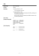
ESC W xL xH yL yH dxL dxH dyL dyH [Function] Defining the print area in PAGE MODE [Code] <1B>H<57>H [Range] 0 xL, xH, yL, yH, dxL, dxH, dyL, dyH 255, except for dxL = dxH = 0 or dyL = dyH = 0 [Outline] Defines the location and size of the print area.
• The figure below illustrates the print area, where X = horizontal start point, Y=vertical start point, Dx=horizontal length, and Dy=vertical length. Print Area < Paper Paper Feed Direction The printable area for this printer is approximately 72.070 mm (576/203 inches) horizontally and 117 mm (1662/360 inches) vertically.
ESC \ nL nH [Function] Specifying the relative position [Code] <1B>H<5C>H [Range] 0 nL 255 0 nH 255 [Outline] This command specifies the next print start position in a relative position with respect to the current position. The next print start position will be at a point of [(nL + nH × 256) × basic calculation pitch] inches away from the current position. [Caution] • Specification of a position outside the print area is ignored.
ESC a n [Function] Aligning the characters [Code] <1B>H<61>H [Range] 0 n 48 [Outline] n 2 50 All the printed data within one line are aligned in the specified position. • Depending on the value “n”, positional alignment is carried out as shown in the table below: n 0,48 1,49 2,50 [Caution] Position Left end alignment Centering Right end alignment • This command is valid only when it is inputted at the beginning of a line. • This command does not affect the PAGE MODE.
ESC c 3 n [Function] Selecting the Paper Sensor valid for a paper end signal output [Code] <1B>H<63>H<33>H [Range] 0 [Outline] This command selects by which Paper Sensor a paper end signal should be output.
ESC c 4 n [Function] Selecting the Paper Near-end Sensor valid for print stop [Code] <1B>H<63>H<34>H [Range] 0 [Outline] This command selects the Paper Near-end Sensor which helps to stop printing when the paper supply almost runs out.
ESC c 5 n [Function] Enabling/Disabling the panel switches [Code] <1B>H<63>H<35>H [Range] 0 [Outline] Enabling/disabling the FEED switch. n 255 • “n” is valid only in the lowest bit. n0 0 1 Condition FEED switch valid FEED switch invalid [Caution] When the panel switch is disabled with this command, the FEED switch is also disabled. Therefore, the paper cannot be fed by operating the FEED switch.
ESC d n [Function] Printing and feeding the paper by “n” lines [Code] <1B>H<64>H [Range] 0 [Outline] Prints data in the print buffer and feeds paper by “n” lines. n 255 • Specified lines do not remain. • The beginning of the line is specified as the next print start position. [Caution] If [n × line feed width] exceeds approximately 1016 mm, this command feeds paper by approximately 1016 mm (40 inches). [Default] The initial value is not defined.
ESC n n [Function] Setting a remaining amount of printout [Code] <1B>H<6E>H [Range] 0 [Outline] This command sets the remaining amount of printing after detecting paper near end 1. n is set in cm. [Caution] • If the paper near end (PNE) sensor is disabled, this command has no function. n 255 (“n” in the 2nd byte denotes this command.) • The set value and the remaining amount of printing are not cleared by the initialize command (ESC @).
ESC t n [Function] Selecting the character code table [Code] <1B>H<74>H [Range] 0 [Outline] Selecting the character code table: n 9, n = 255 The character code table is selected based on the value of “n”.
ESC { n [Function] Specifying/Canceling the inverted characters [Code] <1B>H<7B>H [Range] 0 [Outline] Specifying/canceling inverted characters. n 255 • “n” is valid only for the lowest bit (n0). • Control by the lowest bit (n0) is shown as follows: [Caution] n0 Condition 0 1 Canceling inverted characters. Specifying inverted characters. • Inverted printing means printing the line turned 180°. • This command is valid only when it is specified at the beginning of a line.
GS ! n [Function] Specifying the character size [Code] <1D>H<21>H [Range] [Outline] 0 n 1 vertical magnification 1 horizontal magnification 255, where: 0 1 2 3 4 5 6 7 Function 112 [Caution] Value Hex. Number Decimal Number Vertical magnification specification Refer to Table 2, “Vertical Magnification”. Horizontal magnification specification Refer to Table 1, “Horizontal Magnification”.
• If characters of different vertical magnification are contained in a line, the baseline of each character is lined up. • Horizontal and vertical magnification can also be specified/ canceled by ESC !. The ESC ! or GS ! command, whichever is handled last, becomes effective.
GS $ nL nH [Function] Specifying the absolute vertical position of characters in PAGE MODE [Code] <1D>H<24>H [Range] 0 nL 255 0 nH 255 [Outline] This command is used in PAGE MODE to specify the vertical position of characters at the data mapping start position as an absolute value measured from the start point. The vertical position of a character at the next data mapping start position will be at a point [(nL + nH × 256) × basic calculation pitch] inches away from the start point.
GS * n1 n2 [ d ] n1×n2×8 [Function] Defining the download bit image [Code] <1D>H<2A>H [< d >] n1 × n2 × 8 [Range] 1 n1 255 1 n2 48 n1 × n2 0 [Outline] d 1536 255 Defines download bit images of the number of dots specified by n1 and n2. • The numbers of dots are n1 × 8 in horizontal direction and n2 × 8 in vertical direction. • ”d” indicates bit image data. • Once defined, the download bit image remains effective until redefinition, ESC @ execution, ESC &, or power OFF takes place.
[Sample Program] GOSUB IMG LPRINT CHR$(&H1D) + “/” + CHR$(0); LPRINT CHR$(&H1D) + “/” + CHR$(1); LPRINT CHR$(&H1D) + “/” + CHR$(2); LPRINT CHR$(&H1D) + “/” + CHR$(3); END IMG: n1=10 : n2=5 LPRINT CHR$(&H1D) + “ ”; LPRINT CHR$(n1) + CHR$(n2); FOR J=1 TO n1 8 FOR I=1 TO n2 LPRINT CHR$(J); NEXT I NEXT J RETURN * * [Print Results] ← NORMAL MODE ← DOUBLE WIDTH MODE ← DOUBLE HEIGHT MODE ← QUADRUPLE MODE — 57 —
GS ( A pL pH n m [Function] Execution of test printing [Code] <1D>H<28>H<41>H [Definition] [Outline] (pL+(pH × 256))=2 (pL=2, pH=0) 0 n 1 m 2, 48 3, 49 n m 50 51 Specified test printing will be executed. • pL, pH will specify the number of subsequent parameters by (pL+(pH × 256))bytes. • n will specify the paper for test printing in the following table.
GS / m [Function] Printing the downloaded bit image [Code] <1D>H<2F>H [Range] 0 m 48 [Outline] 3 m 51 Prints downloaded bit image in a mode specified by “m”. Modes that can be selected by “m” are shown below.
GS : [Function] Starting/Ending macro definition [Code] <1D>H<3A>H [Outline] Specifying starting/ending macro definition. Reception of this command during macro definition signifies ending the macro definition. [Caution] Maximum content available for macro definition is 2048 bytes. A portion exceeding 2048 bytes is not defined. • Even with ESC @ (Initialization of the printer) having been executed, defined content is not cleared.
GS A m n [Function] Correcting the position of black mark top position [Code] <1D>H<41>H [Range] m=0, 0 [Outline] This command sets the top position of the black mark with the amount of correction set for the default position. m0 0 [Caution] n 255 Direction Corrects in the forward direction. • This command is valid only when selecting the black mark.
GS B n [Function] Specifying/Canceling the black/white inverted printing [Code] <1D>H<42>H [Range] 0 [Outline] This command specifies or cancels the black/white inverted printing. n 255 • “n” is valid only for the lowest bit (n0). • Control by the lowest bit (n0) is shown as follows: n0 0 1 [Caution] Function The black/white inverted printing is canceled. The black/white inverted printing is specified. • Number “n” is only valid in the lowest bit.
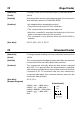
GS H n [Function] Selecting of printing position of HRI characters [Code] <1D>H<48>H [Range] 0 n 48 [Outline] n 3 51 Selecting printing position of HRI characters in printing bar codes. • “n” means the followings. n 0,48 1,49 2,50 3,51 [Caution] Printing Position No printing Above the bar code Below the bar code Both above and below the bar code • The HRI characters refer to the bar code-turned characters so that you can read them.
[Print Results] No HRI characters Printed above Printed below Printed above and below — 64 —
GS I n [Function] Sending the printer ID [Code] <1D>H<49>H [Range] 1 [Outline] Sends the specified printer ID. n n 1,49 2,50 3,51 3 49 n 51 Type of printer ID Model ID Type ID ROM version ID Specification Value (Hex.
GS L nL nH [Function] Setting the left margin [Code] <1D>H<4C>H [Range] [Outline] 0 nL 255 0 nH 255 This command sets the left margin specified by nL and nH. The value of the left margin is [(nL + nH × 256) × basic calculation pitch] inches. Printable Area Left Margin [Caution] Print Area Width • This command only works when it is entered at the beginning of a line. • When PAGE MODE is selected, this command only executes the internal flagging of the printer.
• When mapping non-character data (Bit image, downloaded bit image, or bar code), if the print area specified is narrower than 9-bits, only the line for that data is handled as follows: (1) The print area is extended toward the left (So, the left margin is decreased) until it is 9-dot wide, but not wider than the printable area.
GS P x y [Function] Specifying the basic calculation pitch [Code] <1D>H<50>H [Range] [Outline] 0 x 255 0 y 255 This command sets the horizontal basic calculation pitch to approx. 25.4/x mm (1/x inches), and the vertical basic calculation pitch to approx. 25.4/y mm (1/y inches). • If x = 0, the horizontal basic calculation pitch is reverted to the default value. • If y = 0, the vertical basic calculation pitch is reverted to the default value.
GS R 0 n [Function] Collecting receipts [Code] <1D>H<53>H<30>HH [Range] n=0 [Outline] • This command is valid only when the collection function of the DIP switch is enabled. • This command is ignored in any of the following cases. (1) There is no paper in the presenter. The state where no eject command is received or receipt has already been removed. (2) A command related to the next printing has been received. The state where a command related to the next printing has already been received.
GS R 1 n [Function] Setting receipt collection timer [Code] <1D>H<53>H<31>H [Range] 0 [Outline] • This command is valid only when the collection function of the DIP switch is enabled. n 9 • This command sets the wait time till the receipts are collected automatically. • If n=1 to 9, n × 2.5 sec is set. If n=0, receipts are not collected automatically. • This command is ignored in any of the following cases. (1) There is no paper in the presenter.
GS S [Function] Detecting a black mark [Code] <1D>H<53>H [Outline] • This command is valid only when a black mark is set in the paper selection with DIP switch. • Entering this command allows detection of a black mark. • When a black mark is detected, the print paper is cut and ejected. • Also at the time of printer power on, a black mark is detected and the print paper is cut and ejected. (Settable with DIP switch) • If the 18-in.
GS V m ......... (1) GS V m n ..... (2) [Function] Cutting the paper [Code] (1) <1D>H<56>H (2) <1D>H<56>H [Range] (1) m = 0, 1, 48, 49 (2) m = 65, 66 0 [Outline] n m 0,1,48,49 65,66 [Caution] 255 Performs the specified paper cutting. Function Paper cut (full cut) (Leaving a bridge area uncut) Paper feed by “cut position + {n × basic calculation pitch}”and paper cut (full cut) (Leaving a bridge area uncut) • Fully cut for the label sheet specs.
GS W nL nH [Function] Setting the print area width [Code] <1D>H<57>H [Range] [Outline] 0 nL 255 0 nH 255 Sets the print area width specified by nL and nH. • The print area width will be [(nL + nH × 256) × basic calculation pitch] inches. Printable Area Left Margin [Caution] Print Area Width • This command only works when it is entered at the beginning of a line. • When PAGE MODE is selected, this command only executes the internal flagging of the printer.
(2) If a sufficient area cannot be provided as a result of step (1), the print area is extended toward the left (So, the left margin is decreased). Printable Area A Left Margin (1) Extended toward the right (2) The left margin is trimmed Print Area Width (3) If a sufficient area cannot be provided as a result of step (2), the right spacing is trimmed.
GS \ nL nH [Function] Specifying the relative vertical position of a character in PAGE MODE [Code] <1D>H<5C>H [Range] 0 nL 255 0 nH 255 [Outline] This command is used in PAGE MODE to specify the vertical position of a character in the data mapping start position, in a relative position with respect to the current position. The next data mapping start position will be at a point [(nL + nH × 256)× basic calculation pitch] inches away from the current position.
GS ^ n1 n2 n3 [Function] Executing the macro [Code] <1D>H<5E>H [Range] [Outline] 0 n1 255 0 n2 255 0 n3 1 Executing contents defined in macro. n1 : The number of times of macro execution n2 : Waiting time on macro execution Waiting time of n2 × 100 msec is given for every execution. n3 : Macro execution mode n3=0 Continuous execution: The Macro is executed “n1” times continuously at the time interval specified by “n2”.
GS a n [Function] Enabling/Disabling ASB (Automatic Status Back) [Code] <1D>H<61>H [Range] 0 [Outline] This command selects the status item to be addressed by ASB (Automatic Status Back.) n Bit 0 1 2 3 4 5 6 7 [Caution] 255 Status item addressed by ASB Undefined Online/offline status = disabled Online/offline status = enabled Error status = disabled Error status = enabled Continuous Paper Sensor = disabled Continuous Paper Sensor = enabled Undefined Undefined Undefined Undefined Hex.
(1) 1st byte (Printer information) Bit 0 1 2 3 4 5 6 7 Status Unused Unused Unused Online status Offline status Unused Unused Not in paper feed state triggered by FEED switch In paper feed state triggered by FEED switch Unused Hex. 00 00 00 00 08 10 00 00 40 00 Decimal 0 0 0 0 8 16 0 0 64 0 Hex.
(3) 3rd byte (Paper Sensor information) Bit 0 1 2 3 4 5 6 7 Status Hex.
GS f n [Function] Selecting the font of HRI characters [Code] <1D>H<66>H [Range] n = 0, 1 [Outline] Selecting the font of HRI characters in printing bar code. The type of font can be selected with “n” as follows: n 0, 48 1, 49 Font Font A (12 × 24) Font B (9 × 24) The HRI characters refer to the bar code-turned characters so that you can read them. [Caution] The HRI characters are printed at the position specified with GS H.
GS h n [Function] Specifying the height of the bar code [Code] <1D>H<68>H [Range] 1 [Outline] Selecting bar code height. n 255 “n” denotes the number of dots in the vertical direction. [Default] n = 162 [Sample Program] Refer to Sample Program and Print Results for GS w on page 93.
GS k m [d1 ..... dk] NUL GS k m n [d1 ...... dn] [Function] Printing the bar code [Code] (1) <1D>H<6B>H [d1.....dk] NUL (2) <1D>H<6B>H [d1....dn] [Range] (1) 0 (2) 65 [Outline] m 6 m The definitions of “k” and “d” vary with the bar code system. 73 The definitions of “n” and “d” vary with the bar code system. Selects a bar code system and prints the bar code.
[Caution] For (1): • This command ends with a NUL code. • For UPC-A or UPC-E, the bar code is printed when 12 bytes of bar code data have been entered, and the subsequent data is handled as normal data. • For JAN13, the bar code is printed when 13 bytes of bar code data have been entered, and the subsequent data is handled as normal data. • For JAN8, the bar code is printed when 8 bytes of bar code data have been entered, and the subsequent data is handled as normal data.
For PAGE MODE: • This command only maps the bar code, without performing a printout. After the bar code is mapped, the dot next to the last data item of the bar code is taken as the start position for the next data mapping. • If “d” is out of the range, the processing of the command is aborted, and the subsequent data is handled as normal data. In this case, the data mapping start position does not move.
[Description of Bar Codes] UPC-A This bar code, consisting of numerals only, has a fixed length of 12 columns; a 11-column number entered from the host or application software plus a check digit (12th column) automatically calculated inside the printer. If the 12th-column numeral is sent from the host, the entire bar code will be printed as it is.
CODABAR (NW-7) This bar code, consisting of alphanumerics, has a variable length of columns. Available characters include “0 1 2 3 4 5 6 7 8 9 A B C D $ + – . / :”. A start/stop code is required; any one of A, B, C, and D is used. CODE93 Control character ASCII Hex. NUL 00 SOH 01 STX 02 ETX 03 EOT 04 ENQ 05 ACK 06 BEL 07 BS 08 HT 09 LF 0A VT 0B FF 0C CR 0D SO 0E SI 0F This bar code, consisting of alphanumeric and control characters, has a variable length of columns.
CODE128 This bar code consists of 103 bar code characters and three code sets, enabling 128 ASCII code characters to be printed. It has a variable length of columns. • Code set A ASCII characters 00H - 5FH can be represented. • Code set B ASCII characters 20H - 7FH can be represented. • Code set C Two-digit numbers 00 - 99 can each be represented by one character.
Special characters Hex. 7B53 7B41 7B42 7B43 7B31 7B32 7B33 7B34 7B7B ASCII {S {A {B {C {1 {2 {3 {4 {{ Code set A SHIFT –N/A CODE B CODE C FNC1 FNC2 FNC3 FNC4 ‘{‘ Code set B SHIFT CODE A –N/A CODE C FNC1 FNC2 FNC3 FNC4 ‘{‘ Code set C –N/A CODE A CODE B –N/A FNC1 –N/A –N/A –N/A ‘{‘ To print “No.” in code set B, followed by “123456” in code set C, send the following data string: GS k <73><10><7Bh 42h> “No.
[Description of Bar Codes] UPC-A, UPC-E, JAN-13 (EAN), JAN-8 (EAN), CODE39, ITF, CODABAR, CODE93, CODE128 Type Print Sample Outline of Symbol UPC-A 12-column fixed-length bar code consisting of numerals only. UPC-E 8-column fixed-length bar code consisting of numerals only. Abbreviated version of UPC-A. JAN-13 13-column fixed-length bar code consisting of numerals only. JAN-8 8-column fixed-length bar code consisting of numerals only.
GS r n [Function] Sending status [Code] <1D>H<72>H [Range] n=1, 49 [Outline] Sends the specified status to the host. n 1,49 [Caution] Function Sends the paper Sensor status. • When the serial interface is used: For DTR/DSR control: The printer sends the status after verifying that the host is ready to receive. If the host is not ready to receive, the printer waits for the host to become ready to receive.
GS v 0 m xL xH yL yH d1...dk [Function] Printing of raster bit image [Code] <1D>H<76>H<30>H [] k [Range] 0 m 3, 48 0 yL 255, 0 m yH 51, 0 8, 0 xL d 255, 0 xH 255, 255, k=(xL+xH × 256) × (yL+yH × 256), however, k≠0 [Outline] Prints raster bit images in mode “m”.
• If this command is executed during macro definition, the macro definition is suspended, and the processing of the command starts. The macro is left undefined. • “d” denotes defined data. Dots to be printed are specified as “1”, and those not to be printed as “0”.
GS w n [Function] Specifying the horizontal size (Magnification) of bar code [Code] <1D>H<77>H [Range] 2 [Outline] Selecting bar code width. n 6 “n” denotes the number of dots in fine element width.
FS g3 m a1 a2 a3 a4 nL nH d1…dk [Function] Writing data into the download user NV memory [Code] <1C>H<67>H<33>HHHHHH HH[]nL+(nH × 256) [Range] m=0 6000H (a1+(a2 × 256)+(a3 × 65536)+(a4 × 16777216)) Sto rage start address (nL+(nH × 256)) 7FFFH 1024 k=(nL+(nH × 256)) [Outline] This command loads data into the download user NV memory. • “m” is fixed at 0. • a1, a2, a3, a4 set the data storage start address at (a1+(a2 × 256)+(a3 × 65536)+(a4 × 16777216)).
[Caution] • Because frequent writing in the non-volatile memory can destroy the memory, the writing command (FS g3) should be used less than 10 times a day. • It may happen that the printer becomes BUSY during the process of writing data into the non-volatile memory while this command is executed. When the printer becomes BUSY, it will stop receiving data. Therefore, sending data from the host (Including real time commands) is prohibited.
FS g4 m a1 a2 a3 a4 nL nH [Function] Reading data from the download user NV memory [Code] <1C>H<67>H<34>HHHHHH HH [Range] m=0 6000H (a1+(a2 × 256)+(a3 × 65536)+(a4 × 16777216)) Write start address +n1+nH × 256 8000H K=(nL+(nH × 256)) 7FFFH [Outline] • This command reads data from the download user NV memory. • “m” is fixed at 0. • a1, a2, a3, a4 set the data sending start address at (a1+(a2 × 256)+(a3 × 65536)+(a4 × 16777216)).
• When the XON/XOFF control is selected, all the codes are sent continuously without verifying that the host can receive the data. Data that has been sent is always continuous except for the XOFF code. • When parallel interface is used, the size of the buffer for sending data (The buffer that stores all data to be sent except for ASB status) is 99 bytes. Data which exceeds 99 bytes, will be discarded. • Data can be written into the download user NV memory using the FS g3 command.
FS pnm [Function] Printing the download NV bit images [Code] <1C>H<70>H [Range] 1 n 255 0 m 3 48 [Outline] m 51 This command prints the download NV bit images (n) using a specified mode (m). m 0,48 1,49 2,50 3,51 Dot Density in Vertical Direction NORMAL MODE 203 DPI DOUBLE WIDTH MODE 203 DPI DOUBLE HEIGHT MODE 101 DPI QUADRUPLE SIZE MODE 101 DPI Mode Name Dot Density in Horizontal Direction 203 DPI 101 DPI 203 DPI 101 DPI •“n” denotes the number of the download bit image.
• When the size of a bit image exceeds the limits of the printing area, the data within the limits of the printing area will be printed but the parts exceeding the limit will not be printed. • Regardless of the amount of line feed set with ESC 2 and ESC 3, NORMAL MODE and DOUBLE WIDTH MODE execute a paper feed of (Height n of NV bit image) dots while DOUBLE HEIGHT MODE and QUADRUPLE SIZE MODE execute a paper feed of (Height n of NV bit image × 2) dots.
F S q n [xL xH yL yH d1…dk] 1… [xL xH yL yH d1…dk] n [Function] Defining the download NV bit image [Code] <1C>H<71>HH{}1... {}n [Range] 1 n 0 xH 255, 0 3 but, 1 xL 0 yL 255 0 yH 1 but, 1 0 d 255, (xL + xH × 256) 1023 (yL + yH × 256) 288 255 k = ( xL + xH × 256) × ( yL + yH ×256) × 8 Total definition area = 2M bit (256K bytes) [Outline] This command defines the specified NV bit image.
• If outside-defined-area arguments are processed for the second or subsequent NV bit image data groups, the processing of this command is suspended, and a writing process into the non-volatile memory starts. At this time, the NV bit image being defined becomes invalid (Undefined), but the preceding NV bit images are valid. • “d” denotes the definition data. Bits which correspond to dots to be printed are represented as 1, and those not to be printed as 0.
[Caution] • Because frequent writing in the non-volatile memory can destroy the memory, the writing command should be used less than 10 times a day. • Just after the completion of the writing operation into the nonvolatile memory, the printer hardware will be reset. Therefore, download characters, download bit images, and macro definition will be made undefined. The receiving buffer/printer buffer will be cleared, and each setting will go back to its default value.