
User Manual
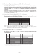
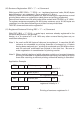
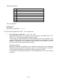
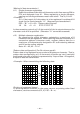
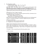
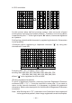
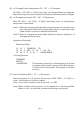
Table Of Contents
- AD-1192 Instruction cover.pdf
- AD-1192 Instruction Manual.pdf
- AD-1192 Instruction cover.pdf
- AD-1192 Instruction Manual.pdf
- WEEE MARK
- CE Marking Declaration of Conformity
- FCC Declaration of Conformity
- Compliance Statements
- SAFETY PRECAUTIONS
- THE TABLE OF CONTENTS
- 1. INTRODUCTION
- 2. TYPE CLASSIFICATIONS
- 3. EXTERNAL APPEARANCE AND PART DESCRIPTIONS
- 4. OPERATIONS
- 5. PARALLEL INTERFACE
- 6. SERIAL INTERFACE
- 7. DIP SWITCH SETTING
- 8. PRINT CONTROL FUNCTION
- 9. CHARACTER CODE TABLE
- 9.1 ASCII + 910 Emulation (International)
- 9.2 910 Emulation (Japan)
- 9.3 Codepage PC437 (USA, Standard Europe)
- 9.4 Katakana
- 9.5 Codepage PC858 (Multilingual)
- 9.6 Codepage PC860 (Portuguese)
- 9.7 Codepage PC863 (Canadian-French)
- 9.8 Codepage PC865 (Nordic)
- 9.9 Codepage PC852 (Eastern Europe)
- 9.10 Codepage PC866 (Russian)
- 9.11 Codepage PC857 (Turkish)
- 9.12 Codepage WPC1252 (Windows Latin1)
- 9.13 Codepage PC864 (Arabic)
- 9.14 Codepage PC869 (Greek)
- 9.15 International Character Code Table
- 10. EXTERNAL DIMENSIONS
— 41 —
2. For 40-column model
In 910 emulation (ESC + “&” + C1 + A1 + A2)
In 3110 emulation (ESC + “&” + A1 + A2)
With ESC (1BH) + ”&” (26H) + {C1} + A1 + A2 code and the pattern data
following input, a pattern is registered. Only 910 emulation for { }.
Total 224 characters are available for registration into addresses of 20H~FFH.
When two pattern data have registered in the same address, those initially
registered are cleared and the new data alone are made valid.
[Recognition of use of upper most bit]
For recognition of use or non-use of the uppermost bit by a character to be
registered, set data to Parameter C1.
C1=0 (00H): Uppermost bit not used.
Other than C1=0: Uppermost bit used.
With 0 set to this parameter while the uppermost bit is in use, ×4 enlargement
results in incomplete images for which the uppermost part is lacking.
[Setting of addresses]
A1 : Registration starting address (20H~FFH)
A2 : Registration ending address (20H~FFH)
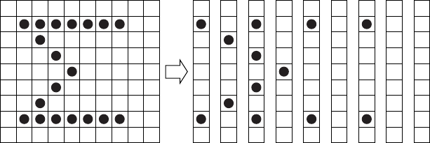
[Pattern data configuration] (For 40-column model)
Pattern data to be registered must consist of 9 bytes per character. That is,
pattern data configured by 9 × 8 dot matrix is broken up into 9 vertically
each of which is represented by 1 byte of data. All together, 9 bytes of data
are transmitted.
<Example> When transmitting the following pattern data:
In 910 emulation
321 654
1
2
3
4
5
6
7
0
1 2 3 4 5 6 7 8 987 9
41H 22H 55H 08H 41H 00H 41H 00H 00H
*
*
*
*
*
*