
Specifications


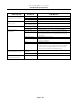


Page 26
S6162-BS-MMC-010/12489
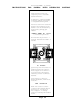
AIR SWITCH ADJUSTMENT
ELECTRIC ONLY
1. Shut off current; disconnect leads and remove air switch.
2. Lay air switch assembly on flat surface. Adjust air blade at “A” (Fig. 1) so that air
blade lays flat and surface “B” is parallel to the flat surface.
3. Place 3/8” x 5/8” spacer bar or equivalent “C” (Fig. 2) under air blade in position
shown; hold switch mounting bracket firmly and adjust switch actuator “D” with
needle nose pliers at “E” by twisting actuator right or left whichever is needed so
that switch closes when end of air blade engages bar “C”.
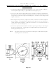
4. Maximum opening or air switch must be no greater than 3/4” (Fig. 3). Bend tab “F”
in or out to maintain this dimension.
5. Re-install air switch assembly on rear of dryer.
6. Re-check operation of air blade. Switch must close before air blade engages face or
opening and re-open before stop “F” engages.