
Specifications


Page 15
S6162-BS-MMC-010/12489
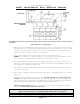
GENERAL INSTALLATIONS
The construction of Cissell Cabinet Dryers permits installation side by side to save space or to provide a wall
arrangement. Position dryer for the least amount of exhaust piping and elbows, and allow free access to the
rear of dryer for future servicing of belts, pulleys, and motor.
Before operating dryer, open basket door, remove blocking between front panel and basket; remove all tape used
to secure dryer parts during shipment; level dryer; and read all instruction tags, etc.
DRYER AIR FLOW INSTALLATION
Nothing is more important than air flow for the proper operation of a clothes dryer. A dryer is a pump which
draws make-up air from the out-of-doors, through the heater, through the clothes and then forces the air
through the exhaust duct back to the out-of-doors. Just as in a fluid water pump, there must be a fluid air flow
to the inlet of the dryer if there is to be the proper fluid air flow out of the exhaust duct. In summary, there
must be the proper size out-of-doors inlet air opening (4 to 6 times the combined areas of the air outlet) and an
exhaust duct size and length which allows flow through the dryer with no more than 0.3 inches water column
static pressure in the exhaust duct.
CISSELL WILL PROVIDE FREE ENGINEERING ADVICE FOR ANY
SPECIFIED INSTALLATION
In some instances, a ventilation system with special fans are required to supply make-up air and/or boost
exhaust fans.
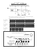
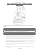
EXHAUSTING DUCT
If needed, use adapter to increase 8” dia. duct to 12” dia. duct. Vent the 8” dia. exhaust, on rear of dryer, to
atmosphere. Do not reduce duct size. If vent is vertical through through roof, install two elbows on the dis-
charge end forming a “U” looking down; if vent is horizontal through wall, install one elbow on the discharge end
looking down to prevent wind, rain, snow, sleet, etc., from entering duct and flowing down to dryer.
For multiple dryer installations, it is preferable to vent each dryer individually with a separate duct.
When conditions require the use of a single exhaust duct for several dryers, piping from each dryer should enter
the single duct at an angle of approximately 30°-45°, and in the direction of the air flow. The cross sectional
area of the single exhaust duct should equal the combined areas of the dryer ducts connected to it. Make all
exhaust connections with the least amount of elbows to reduce air resistance to a minimum. Provide cleanout
and inspection openings in the horizontal sections of the duct work and clean periodically. On multiple installa-
tions employing a single exhaust duct, there should be no back draft to interfere with the normal free discharge
of air from each dryer.
Before approving duct installation, place each dryer in operation; progressively open each dryer door, manually
trip door switch, and see that air is drawn into the basket door opening as freely as it is when all other dryers
are stopped.
Keep the exhaust ducts clean. Do not install wire mesh or screen in the exhaust ducts as lint will build up and
prevent discharge of air from dryers. Keep inside surfaces smooth. Pop rivets are recommended for duct
assembly.
MAKE-UP AIR
If possible, provide opening to the room where the dryer is a minimum of 2 square feet make-up air for each
dryer.
TROUBLESHOOTING
Scorched clothes, slow drying, lint accumulations, or air switch malfunction are indicators of exhaust and/or
make-up air problems.