50 lb. Sectionalized Shipboard Laundry Dryer Models L36TD30ME, L36TD30MS (NSN: 3H 3510-01-340-9419) (NSN: 3H 3510-01-312-4422) 440V. A.C. 60 CYCLE 3 PHASE TECHNICAL INSTALLATION SERVICE CISSELL MANUFACTURING OPERATION PARTS COMPANY HEADQUARTERS 831 SOUTH FIRST ST. P.O. BOX 32270 LOUISVILLE, KY 40232-2270 THIS MAN344 MANUAL 1/98 - 5C - WB MANUAL PHONE: (502) 587-1292 SALES FAX: (502) 585-3625 SERVICE/PARTS FAX: (502) 681-1275 MUST BE GIVEN TECHNICAL TO MANUAL THE EQUIPMENT OWNER.
S6162-BS-MMC-010/12489 IMPORTANT NOTICES—PLEASE READ For optimum efficiency and safety, we recommend that you read the Manual before operating the equipment. Store this manual in a file or binder and keep for future reference. WARNING: For your safety, the information in this manual must be followed to minimize the risk of fire or explosion or to prevent property damage, personal injury, or loss of life.
S6162-BS-MMC-010/12489 WARNING: To avoid fire hazard, do not dry articles containing foam rubber or similar texture materials. Do not put into this dryer flammable items such as baby bed mattresses, throw rugs,undergarments (brassieres, etc.) and other items which use rubber as padding or backing. Rubber easily oxidizes causing excessive heat and possible fire. These items should be air dried. WARNING: Synthetic solvent fumes from drycleaning machines create acids when drawn through the dryer.
S6162-BS-MMC-010/12489 CISSELL DRYER WARRANTY The Cissell Manufacturing Company (Cissell) warrants all new equipment (and the original parts thereof) to be free from defects in material or workmanship for a period of two (2) years from the date of sale thereof to an original purchaser for use, except as hereinafter provided.
S6162-BS-MMC-010/12489 TABLE OF CONTENTS 50 LB. SECTIONALIZED SHIPBOARD LAUNDRY DRYER PAGE Model Numbers & Company Address ....................................................... 1 Important Notices ..................................................................... 2-3 Dryer Warranty ........................................................................ 4 Table of Contents ...................................................................... 5 Warnings, Cautionary Notes and Symbols ...................
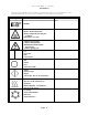
S6162-BS-MMC-010/12489 SYMBOLS The following symbols are used in this manual and/or on the machine. The numbers between () refer to the numbers on the machine surveys.
S6162-BS-MMC-010/12489 SYMBOLS Symbol Description rotation in two directions rotation dans les deux sens Drehbewigung in zwei Richtungen movimiento rotativo en los dos sentidos direction of rotation sens de mouvement continu de rotation Drehbewegung in Pfeilrichtung movimiento giratorio o rotatorio en el sentido de la flecha End of Cycle caution attention Achtung atencion; precaucion Page 7 Part/Measurement
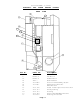
S6162-BS-MMC-010/12489 ELECTRIC AND STEAM HEATED FRONT DRYERS VIEW Ref. No. Part No. Description 1 2 3 4 5 6 7 8 9 TU10528 PT111 TU5004 FG147 TU5421 TU5421 TU4862 TU10521 TU5261 Thermometer for Basket Temp.
S6162-BS-MMC-010/12489 ELECTRIC AND STEAM HEATED REAR DRYERS VIEW 20 19 18 17 Ref. No. 10 11 12 13 14 15 16 17 18 19 20 PART NO.
S6162-BS-MMC-010/12489 Page 10
S6162-BS-MMC-010/12489 ELECTRIC HEATED L36TD30ME Heat Capacity ........................... Net Weight (approx.) ...................... Domestic Shipping ........................ Weight (carton approx.) Export Shipping .......................... (1 box approx.) Export Shipping Dimensions ................ Export Crating ........................... BASKET LOAD 36KW 790 lbs. 1050 lbs. 1200 lbs. 88” (L) x 45” (W) x 58” (H) 148cu.ft. CAPACITY ................. 50 LBS.
S6162-BS-MMC-010/12489 BREAK DOWN PROCEDURE If the tumbler dryer is installed aboard ship, disconnect the electrical power leads and steam connections going to the dryer before proceeding further. NOTE: All wiring is to be left in place unless otherwise noted. Thermometer and thermostat assembly is left in place. Back channel, gear reducer, belt guard and motor assembly remains as one complete assembly. 1.
BREAK S6162-BS-MMC-010/12489 DOWN PROCEDURE (Continued) 7. Go to rear of dryer and remove top cover (10) (Electric Dryer Only) by unscrewing 2 hex head bolts, then lift top up and pull top to rear of dryer and remove. Now you are ready for dismantling the dryer. 8. Unscrew twenty-eight 1/4” and four 3/8” hex head bolts holding top compartment (11) to dryer. Remove top compartment.
BREAK S6162-BS-MMC-010/12489 DOWN PROCEDURE (Continued) 9. Go to the rear of dryer and unscrew fourteen 3/8” nuts holding rear channel, motor and gear reducer assembly (12) to the dryer. 10. You can remove either the right section (13) or left section (14) next. Going to front of dryer, unscrew sixteen 1/4” hex head bolts holding either section to the base. The bolts are located behind the sweep sheets and both in front and rear of the compartment. 11.
S6162-BS-MMC-010/12489 GENERAL INSTALLATIONS The construction of Cissell Cabinet Dryers permits installation side by side to save space or to provide a wall arrangement. Position dryer for the least amount of exhaust piping and elbows, and allow free access to the rear of dryer for future servicing of belts, pulleys, and motor.
S6162-BS-MMC-010/12489 EXHAUST DUCT INFORMATION For Exhaust Duct less than 14 feet and 2 elbows equivalent and less than 0.3 inches static pressure. DRYER EXHAUSTS Area of section “A-A” must be equal to the sum of dryer exhaust pipes enteringmultipleexhaustpipe.(Seechartbelow.) MODELS: L28FD30, L28US30, L36FD30, L36UR30, L36CD36, L44FD42 No.
S6162-BS-MMC-010/12489 DRYER INSTALLATION WITH MULTIPLE EXHAUST For Exhaust Duct more than 14 feet and 2 elbows equivalent and more than 0.3 inches static pressure. (See illustration on next page.) 1. Make-up air from outside building may enter enclosure from top or side walls. Area of opening should be equal to 4 to 6 times the sum of dryer duct areas. Provide 1 square foot (.1m²) for each 6 inches (15.24 cm) diameter; 2 square feet (.2m²) for each 8 inches (20.3 cm) diameter; and 4 square feet (.
S6162-BS-MMC-010/12489 DRYER INSTALLATION WITH SEPARATE (PREFERRED) EXHAUST For ductwork less than 14 feet and 2 elbows equivalent and less than 0.3 inches static pressure: NEVER exhaust the dryer into a chimney. NEVER install wire mesh screen over the exhaust or make-up air area. NEVER exhaust into a wall, ceiling, or concealed space. 1. Make-Up Air opening from outside the building may enter the enclosure from the top or side walls.
S6162-BS-MMC-010/12489 DRYER AIR FLOW INSTALLATION Nothing is more important than air flow for the proper operation of a clothes dryer. A dryer is a pump which draws make-up air from the out-of-doors, through the heater, through the clothes and then forces the air through the exhaust duct back to the out-of-doors. Just as in a fluid water pump, there must be a fluid air flow to the inlet of the dryer, if there is to be the proper fluid air flow out of the exhaust duct.
S6162-BS-MMC-010/12489 RECOMMENDED STEAM PIPING INSTALLATION ILLUSTRATION Page 20
S6162-BS-MMC-010/12489 OPERATING INSTRUCTIONS Step 1. After loading the dryer tumbler with the washed clothes load, proceed to close the loading door. Step 2. Timer Models - Turn drying timer knob to the desired drying time. Step 3. Temperature Selector - Select temperature per type of load being dried in the dryer. High Heat - mixed and heavy fabrics - 180° F exhaust temperature. Low Heat - poly knit synthetic-blends-light weight fabrics - 160° F exhaust temperature. Step 4.
S6162-BS-MMC-010/12489 Troubleshooting Chart TROUBLE Motor will not start. CAUSE Motor overloads open. Defective Bonnet Hi-H Limit. No power. Incorrect power. Motor tripping on thermal overload. Defective Start Switch. Time off. Loose wiring connections. Defective starting relay. Defective Door Switch. Low voltage. Inadequate wiring. Loose connections. Inadequate air. Basket motor will not run. Poor housekeeping. Defective Basket Motor Contractor. Defective Reversing Timer. Defective motor.
S6162-BS-MMC-010/12489 Troubleshooting Chart TROUBLE Dryer runs, no steam to coils. CAUSE Solenoid valve. Thermostat. Check valve installed incorrectly. Strainer clogged. Water in steam line. Dryer runs no steam to coils. Dryer too hot. Garments too hot at end ofcycle. Steam piping installed incorrectly. Trap not functioning. Valve closed. Steam trap blocked. Inadequate makeup air. Lint accumulated. Exhaust duct dampers. Defective Hi-Lo Switch.
S6162-BS-MMC-010/12489 Troubleshooting Chart TROUBLE Basket motor runs, but basket will not revolve. Dryer does not stop at end of cycle. Basket does not reverse. Dryer noisy or vibrating. CAUSE V-Belt broken. V-Beltloose. Motor pulley loose. Defective timer. Defective ThermO-Cool thermostat. Reversing timer. Reversing timer. Not leveled. Fan out of balance. Basket rubbing. V-Belt sheaves. Belt. Foreign objects. Blower motor will not run (Basket Revolves). Dryer does not stop at end of time period.
S6162-BS-MMC-010/12489 Troubleshooting Chart TROUBLE Dryer runs, but no heat. CAUSE REMEDY Incorrectvoltage. No voltage. Check for correct control voltage - 120V. Check power supply, check secondary voltage on transformer and check wiring and wiring diagram. Close lint door. Clean out lint compartment daily. Check back draft damper for foreign object lint accumulation or other causes that may prevent damper from opening. Check duct work for lint build-up.
S6162-BS-MMC-010/12489 AIR SWITCH ADJUSTMENT ELECTRIC ONLY 1. Shut off current; disconnect leads and remove air switch. 2. Lay air switch assembly on flat surface. Adjust air blade at “A” (Fig. 1) so that air blade lays flat and surface “B” is parallel to the flat surface. 3. Place 3/8” x 5/8” spacer bar or equivalent “C” (Fig.
S6162-BS-MMC-010/12489 Small Gear Reducer Operation and Maintenace BEFORE PLACING THE DRYER IN OPERATION, Remove small screw from vent tube in top rear of each Gear Reducer case. Remove the cork from the oil level inspection cup. If the oil level is correct, the oil level inspection cup will be half filled with oil. If not, add oil. Oil may be added to the Gear Reducer by removing the filler plug in the top rear of the Gear Reducer case.
S6162-BS-MMC-010/12489 REMOVAL AND INSTALLATION OF GEAR REDUCER SEALS NOTE: On original equipment, the Cissell Gear Reducer is equipped with a Garlock Shaft Seal. If this seal requires replacement, it cannot be replaced with the same type of seal since the original seal would have seated in on the shaft. It must be replaced with a TU2166. CAUTION Drain oil before removing seals; replace with NEW oil after installing new seals (See Cissell Gear Reducer Sheet).
S6162-BS-MMC-010/12489 INSTRUCTIONS FOR DRYERS WITH REVERSING IMPORTANT Tumbler Basket must stop completely for 3 to 5 seconds between reversals. In operation, coasting of basket increases, making it necessary to readjust Reversing Timer. Failure to do this will cause the thermal overload units for the basket to cut-out unnecessarily and probably damage gear reducer. FURNAS TIMER NO. L3788 3.2 reversals per minute Minimum OFF adjustment 1.1 seconds. Each division adds 1.2 seconds.
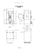
S6162-BS-MMC-010/12489 INSTRUCTIONS FOR ALIGNING BASKET ON CISSELL 50 LB. DRYER DOUBLE MOTOR 1. Loosen the 4 gear reducer mounting bolts (1, 2, 3 & 4) on rear of dryer, and 2 adjusting bolts #5, on gear reducer housing (Fig. 3). 2. Place one “A” and two “B” diameter pins inside the drying compartment between the rim of the basket opening and the rim of the door opening in the positions shown in Figure 1 and Figure 2. Check the two “B” pins for equal clearance. 3.
S6162-BS-MMC-010/12489 BASKET AND SPIDER ASSEMBLY - TU10460 Ref. No. Part No.
S6162-BS-MMC-010/12489 OVERALL Ref. No. Part No.
S6162-BS-MMC-010/12489 OVERALL Ref. No. Part No.
S6162-BS-MMC-010/12489 TOP BOLTED SECTION, ELECTRIC - TU11720 Ref. No. Part No.
S6162-BS-MMC-010/12489 LEFT CENTER BOLTED SECTION - TU11719 Ref. No. Part No.
S6162-BS-MMC-010/12489 RIGHT CENTER BOLTED SECTION STEAM - TU11818 ELECTRIC - TU11718 Ref. No. Part No.
ACCESS Ref. No. Part No.
S6162-BS-MMC-010/12489 THERMOMETER ASSEMBLY - TU10528 Ref. No. Part No.
BOTTOM Ref. No. Part No.
BACK S6162-BS-MMC-010/12489 CHANNEL BOLTED ASSEMBLY - Page 40 TU10600
S6162-BS-MMC-010/12489 BACK CHANNEL Ref. No. Part No.
S6162-BS-MMC-010/12489 FAN ASSEMBLY - TU10575 Ref. No. Part No. 1 2 3 4 5 6 7 8 9 10 11 12 13 14 MTR302 TU10445 TU2473 TU2474 TU5874 TU2476 TU5439 TU2814 VSB130 C249 TU4790 TU4791 504641292 TU4684 Description Quantity Motor, 240/480/60/3 Motor Mount W/A Side Gasket Top & Bottom Gasket Fan, 5/8” Bore Felt Seal 5/16” - 18 x 3/4” Cap Screw 5/16” Lockwasher 5/16” Flat Cut Washer 5/16” - 18 Hex Nut 1/2” Str. Tomic Connector 1/2” 90° Angle Connector Greenfield Cable 3/16” Sq.
S6162-BS-MMC-010/12489 RIGHT HAND FRONT PANEL AND DOOR ASSEMBLY - TU11766 LEFT HAND FRONT PANEL AND DOOR ASSEMBLY - TU11772 Ref. No. Part No.
S6162-BS-MMC-010/12489 INSULATED LINT DOOR - TU10521 Ref. No. Part No.
S6162-BS-MMC-010/12489 PARTS—SMALL GEAR REDUCER—TM100 Quantity 1 2 3 4 5 6 7 8 9 10 11 12 13 14 15 16 17 18 19 20 TM103 TM104 TM105 TM107 TM108 TM101 TM110 TM112 TM115 TM117 TM102 TM120 TU2623 TU2839 TU3243 RC349 TM118 TU4787 TU3211 TM119 Housing Small Seal Small Open End Cap Small Bearing Cup Small Bearing Cone Worm 1-1/2” x 7-1/8” Large Bearing Cup Large End Cap 1/4” Pipe Plug Large Bearing Cone Worm Gear Oil Seal Cap Screw 3/8” - 16 x 1-1/2” Cap Screw 1/4” - 20 x 7/8” 3/8” Internal Tooth Lockwasher 1/
S6162-BS-MMC-010/12489 CONTROL BOX COMPONENT ASSEMBLY STEAM - TU11812 ELECTRIC - TU10453 Ref. No. Part No.
ELECTRONIC Ref. No. Part No.
NINE S6162-BS-MMC-010/12489 SECTION STEAM BONNET ASSEMBLY TU11202 9 Section Steam Bonnet Assembly w/Solenoid Valve 120V Ref. No. Part No. 1 2 3 4 5 6 7 8 10 11 12 13 14 15 TU11203 TU2547 TU2548 TU2413 TU2414 TU2405 TU3124 M263 TU2735 TU4608 TU6041 TU7151 50-4641-292 TU4790 VSB134 Description Quantity Housing Weldment Front Coil Retainer Rear Coil Retainer Steam Coil Manifold 3/4” - 16 x 3/8” Straight Connector Steam Coil 7-3/4” W x 1-5/8” H x 26” Lg. 3/8” - 16 x 3/4” Bolt #8 x 3/8” S. M. S.
S6162-BS-MMC-010/12489 THERMOSTAT ASSEMBLY - TU10796 Ref. No. Part No. 1 2 3 4 5 6 7 8 9 10 11 12 601367512 M270 TU3624 TU5143 TU3400 TU2045 TU3240 TU5149 TU11199 FG148 TU3266 M262 Description Quantity #8 - 32 X 1” Truss Hd.
S6162-BS-MMC-010/12489 Page 50
S6162-BS-MMC-010/12489 Page 51
S6162-BS-MMC-010/12489 Page 52
S6162-BS-MMC-010/12489 Page 53