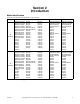
Troubleshooting Drying Tumblers 25 Pound Capacity 30 Pound Capacity 35 Pound Capacity 55 Pound Capacity Starting Serial No. 0602004144 Refer to Page 7 for Model Numbers 1 SELEC TEMP T 2 INSER COIN T 3 PUSH START HIGH TEMP MED TEMP 25 C STAR T LOW TEMP NO HEAT www.comlaundry.com Part No.
Table of Contents Section 1 – Safety Information .......................................................... Locating an Authorized Service Person ............................................... Safety Warnings and Decals................................................................. Safety Precautions for Servicing Tumblers .......................................... 4 6 6 6 Section 2 – Introduction ..................................................................... 7 Model Identification ............
Gas and Steam Models Control Circuit Schematic.................................................................53 Gas and Steam Models Control Circuit Schematic.................................................................54 Gas and Steam Models Control Box Schematic .....................................................................55 Control Box Connection ...................................................................56 Electric Models Control Circuit Schematic...................................
Section 9 – Quantum Control Troubleshooting............................... 126 Models with LC, LX, LY, WC, WX and WY Control Suffixes 50. No Infrared Communication .................................................... 127 51. Coins Ignored When Entered................................................... 128 52. No Display ............................................................................... 129 53. “Door Open” Indicator............................................................. 131 54.
Section 1 Safety Information Throughout this manual and on machine decals, you will find precautionary statements (“CAUTION”, “WARNING”, and “DANGER”) followed by specific instructions. These precautions are intended for the personal safety of the operator, user, servicer, and those maintaining the machine. DANGER Danger indicates an imminently hazardous situation that, if not avoided, will cause severe personal injury or death.
Safety Information IMPORTANT INFORMATION: During the lifetime of a tumbler, it may require service. The information contained in this manual was written and is intended for use by qualified service technicians who are familiar with the safety procedures required in the repair of a tumbler, and who are equipped with the proper tools and testing equipment. NOTE: The WARNING and IMPORTANT instructions appearing in this manual are not meant to cover all possible conditions and situations that may occur.
Safety Information Locating an Authorized Service Person Alliance Laundry Systems is not responsible for personal injury or property damage resulting from improper service. Review all service information before beginning repairs. Warranty service must be performed by an authorized technician, using authorized factory parts. If service is required after the warranty expires, Alliance Laundry Systems also recommends contacting an authorized technician and using authorized factory parts.
Section 2 Introduction Model Identification Information in this manual is applicable to these models: Gas Steam Electric 25 Pound CHD25G2-CA025L CHD25G2-CA025N CHD25G2-CT025L CHD25G2-CT025N CHD25G2-CU025L CHD25G2-CU025N DR25G2-BA025L DR25G2-BA025N DR25G2-BT025L DR25G2-BT025N DR25G2-BU025L DR25G2-BU025N GA025L GA025N GT025L GT025N GU025L GU025N HA025L HA025N HT025L HT025N HU025L HU025N IPD25G2-IT025L IPD25G2-IT025N KA025L KA025N KT025L KT025N KU025L KU025N LA025L LA025N LT025L LT025N LU025L LU025N PA025
Introduction Gas 35 Pound 55 Pound Steam AT035L AT035N CHD35G2-CA035L CHD35G2-CA035N CHD35G2-CT035L CHD35G2-CT035N CHD35G2-CU035L CHD35G2-CU035N DR35G2-BA035L DR35G2-BA035N DR35G2-BT035L DR35G2-BT035N DR35G2-BU035L DR35G2-BU035N GA035L GA035N GT035L GT035N GU035L GU035N HA035L HA035N HT035L HT035N HU035L HU035N IPD35G2-IT035L IPD35G2-IT035N KA035L KA035N KT035L KT035N KU035L KU035N LA035L LA035N LT035L LT035N LU035L LU035N PA035L PA035N PT035L PT035N PU035L PU035N SA035L SA035N ST035L ST035N SU035L S
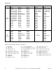
Introduction Serial Plate Location When calling or writing about your product, be sure to mention model and serial numbers. Model and serial numbers are located on serial plate as shown. 1 TMB2098N 1 Serial Plate Customer Service If literature or replacement parts are required, contact the source from which the machine was purchased or contact Alliance Laundry Systems at (920) 748-3950 for the name and address of the nearest authorized parts distributor. For technical assistance, call (920) 748-3121.
Introduction How a Tumbler Works A tumbler uses heated air to dry loads of laundry. 1 When the motor is started, the exhaust fan pulls room temperature air in through the air intake at the rear of the tumbler and over the heat source (burner flame for gas, heating element for electric, and coil for steam). 2 The heated air moves into the cylinder, where it is circulated through the wet load by the tumbling action of the cylinder.
Section 3 Troubleshooting WARNING To reduce the risk of electric shock, fire, explosion, serious injury or death: • Disconnect electric power to the tumbler before servicing. • Close gas shut-off valve to gas tumbler before servicing. • Close steam valve to steam tumbler before servicing. • Never start the tumbler with any guards/panels removed. • Whenever ground wires are removed during servicing, these ground wires must be reconnected to ensure that the tumbler is properly grounded.
Troubleshooting 1. Tumbler Does Not Start Tumbler Does Not Start Is motor relay inoperative? Yes Test relay and replace if necessary. No Is loading door open? Close loading door completely. Yes No Is drying timer in an off position (Hybrid Timer Models)? Yes Turn drying timer on. Check that proper amount of coins are inserted. Is coin drop inoperative? Yes Check power supply, or replace fuses. Yes Close and lock lint panel.
Troubleshooting 2. Motor Does Not Start Motor Does Not Start Is the electrical power off or circuit breaker fuse blown? Is there broken, loose, or incorrect wiring? Yes Refer to wiring diagram. No Yes Check power supply, or replace fuses. Is the fan or fan motor binding? Yes Replace fan or motor assembly. No No Is the loading door switch or lint panel switch not closed or switch inoperative? Yes Close door, panel or test switch and replace if inoperative.
Troubleshooting 3. Motor Overload Protector Cycles Repeatedly Motor Overload Protector Cycles Repeatedly Yes Is voltage correct? No Is clothes load too large? Yes Refer to Installation Manual for electrical requirements. Remove part of load. No Is clothes cylinder binding? Yes Check cylinder for binding. No Check with local power company to ensure that wiring is adequate. Yes Is wiring adequate? No Yes Is make-up air adequate? Refer to Installation Manual for make-up air requirements.
Troubleshooting 4. Motor Runs But Cylinder Does Not Turn Motor Runs But Cylinder Does Not Turn Is cylinder belt broken? Yes Replace cylinder belt. Yes Check cylinder for binding.
Troubleshooting 5. Motor Does Not Stop Motor Does Not Stop Is the door switch or lint panel switch not working properly? Yes Test switches and replace if inoperative. No Is coin drop not working properly? Yes Test coin drop and replace if inoperative. No Is wiring incorrect? Yes Refer to wiring diagram. No Is electronic control inoperative? Yes Replace electronic control. Yes Test relay and replace if inoperative.
Troubleshooting 6. Burner Does Not Ignite Burner Does Not Ignite Is there an improper or inadequate exhaust system? Is stove limit thermostat 2 inoperative? Yes Refer to Installation Manual for exhaust system requirements. Is there an insufficient gas supply? No Are there blown fuses or Yes tripped circuit breakers in external electric supply line? No Check fuses or circuit breaker. No No Is drying selector in the “Cool Down” portion of cycle? Yes Reset switch on microprocessor.
Troubleshooting 6. Burner Does Not Ignite (continued) Continued from previous page Is the airflow switch inoperative? Is there a blown fuse on tumbler? Yes Test switch and replace if inoperative. No Is the lint panel not closed properly? Yes Unlock and open lint panel. Close panel ensuring a tight fit, then lock. No Is there broken, loose or incorrect wiring? Yes Refer to wiring diagram. Check fuse (located in control box) and replace if necessary.
Troubleshooting 6. Burner Does Not Ignite (continued) Continued from previous page Is there an inoperative microprocessor or hybrid timer? Yes Test and replace as needed. No Is wrong transformer configuration harness installed? Yes Check incoming voltage and install correct configuration harness. No Is Instant Electronic Ignition (IEI) control in safety lockout? Yes Reset IEI control by opening and closing loading door. (NonCE models only) Reset IEI by pressing reset button on back of unit.
Troubleshooting 7. Burner Ignites and Goes Out Repeatedly Burner Ignites and Goes Out Repeatedly Is Yes there excessive igniter to burner clearance? Is there insufficient gas pressure? Yes Check gas supply and pressure. Is the cabinet thermostat inoperative? Yes Test thermostat and replace if inoperative.
Troubleshooting 8. Burner Does Not Shut Off Burner Does Not Shut Off Are there impurities on gas valve seat, preventing valve from closing? Yes Replace gas valve. No Is wiring correct? Yes Refer to wiring diagram. No Is control heater relay malfunctioning? Yes Replace control.
Troubleshooting 9. Clothes Do Not Dry Clothes Do Not Dry Is there enough heating time allocated for the load? Yes Start cycle again with enough time to dry load. Does the burner ignite and go out repeatedly? Refer to Paragraph 7. Yes No No Is the burner not igniting? Yes Refer to Paragraph 6. Is the drying selector improperly set? Set selector for higher setting. Yes No No Is there too much water in articles being dried? Is the voltage incorrect? Yes Remove excess water.
Troubleshooting 9. Clothes Do Not Dry (continued) Continued from previous page Is the lint screen clogged? Yes Clean lint screen. Yes Adjust damper so it turns freely. No No Is the thermistor inoperative? Is the exhaust damper binding? Yes Replace thermistor. Is the cylinder speed too fast? Yes Check belt is not riding on outer diameter of motor pulley.
Troubleshooting 10. Tumbler Overheating Tumbler Overheating Does tumbler have incorrect main burner orifices? Is the thermistor sensor inoperative? Yes Obtain and install correct orifices. No Is the exhaust damper binding? No Is gas Yes pressure too high or low? Adjust gas pressure as specified on serial plate. Yes Refer to Installation Manual for make-up air requirements. No Is there lint buildup? Yes Clean lint compartment. Check damper for lint accumulation. Check ductwork for lint buildup.
Troubleshooting 11. Burner Not Burning Properly Burner Not Burning Properly Is there lint/dirt in burner tube? Yes Disassemble burner and blow out the dirt. No No Yes No Is the exhaust duct restricted or blocked? Yes Replace airflow switch. No Is the gas Yes pressure too high or low? Does the tumbler have incorrect orifices? Is the airflow switch not functioning properly? Yes Check serial plate on back of tumbler for correct gas pressure.
Troubleshooting 12. Loading Door Opens During Operation Loading Door Opens During Operation Is tumbler improperly leveled? Yes Refer to Installation Manual for leveling leg adjustment. Yes Remove part of load and restart tumbler. No Is clothes load too large? No Is loading door strike adjusted incorrectly? Yes Refer to Adjustments Section for strike adjustment.
Troubleshooting 13. Cylinder Continues to Spin with Door Open Cylinder Continues To Spin With Door Open Is relay inoperative? Yes Replace relay in control box. TMB1914S NOTE: All tumbler panels must be in place and on the machine for proper operation.
Troubleshooting 14. Coin Does Not Fall into Coin Vault or Coin Drop Sensor Does Not Register that Coin Has Been Entered Coin Does Not Fall Into Coin Vault or Coin Drop Sensor Does Not Register That Coin Has Been Entered Is proper electrical power supplied to coin drop? No Yes Is machine level? No Incorrect electrical connection may prevent coins from registering in coin drop. Refer to wiring diagram. Machines that are not level may prevent coins from following through required check stages of drop.
Section 4 Adjustments WARNING To reduce the risk of electric shock, fire, explosion, serious injury or death: • Disconnect electric power to the tumbler before servicing. • Close gas shut-off valve to gas tumbler before servicing. • Close steam valve to steam tumbler before servicing. • Never start the tumbler with any guards/panels removed. • Whenever ground wires are removed during servicing, these ground wires must be reconnected to ensure that the tumbler is properly grounded. W002 15.
Section 5 Micro Display Control (MDC) Troubleshooting Models with BC, BL, BX and BY Control Suffixes WARNING To reduce the risk of electric shock, fire, explosion, serious injury or death: • Disconnect electric power to the tumbler before servicing. • Close gas shut-off valve to gas tumbler before servicing. • Close steam valve to steam tumbler before servicing. • Never start the tumbler with any guards/panels removed.
Micro Display Control (MDC) Troubleshooting 18. Control Has No Display Control has no display (1) Is there voltage across H1-1 & H1-3 on the control? Gas, steam and electric heat. Single and three phase power supply. (6) YES Replace electronic control. NO Is there voltage at the input of the secondary fuse? NO Correct wiring between secondary fuse and transformer. YES (7) Is there power supplied to the unit? NO Plug unit in and run it.
L2 4 7 SECONDARY FUSE MDL-3.5A 250V 6 2 BLK BLK RED RED RED/WHT 120V 1 N.O. COM LT. BLU 4 2 3 RED/WHT RED/BLU 5 N.O. COM LINT PANEL SWITCH SECONDARY FUSE 1.25 T 250V WHT 24V 1.5A DOOR SWITCH 3 24V 3.
Micro Display Control (MDC) Troubleshooting 19. Door Open Indicator Gas, steam and electric heat. Single and three phase (1) Is there voltage at H2-1 on the Electronic control? Reference voltage checks to transformer neutral. YES Replace Control. NO (6) Is there voltage at the input of the secondary fuse? NO Correct wiring between secondary fuse and transformer. YES (7) Is there power supplied to the unit? NO Plug unit in and run it.
7 L2 SECONDARY FUSE MDL-3.5A 250V 6 2 BLK BLK RED RED RED/WHT FUSE 9 1 N.O. COM LT. BLU 4 2 4 RED/WHT N.O. COM LINT PANEL SWITCH 11 RED/BLU 10 SECONDARY FUSE 1.25 T 250V WHT 24V 1.5A DOOR SWITCH 8 3 120V 250V AGC-2A 24V 3.
Micro Display Control (MDC) Troubleshooting 20. Motor Will Not Start/Run Note: test conducted with vend (1) price satisfied and start button pressed. NO Is there voltage across H2-1 and H2-6 on the electronic control ? Gas, electric and steam heat. Single and three phase power supply. Refer to Door Open Indicator flowchart. Replace MDC control. (6) Is there voltage across terminals 1 & 4 of the fan motor? YES (2) Is there voltage across H2-4 and H2-6 on the electronic control? NO Replace control.
Micro Display Control (MDC) Troubleshooting 20. Motor Will Not Start/Run (continued) (9) Is there voltage across terminals 1 & 4 of cylinder motor? NO Correct wiring between cylinder motor and motor control relay. YES Does the cylinder motor run? NO Replace cylinder motor. YES Motors are operational. Note: For high voltage three phase supply (380 volts or higher), the cylinder and fan motors are supplied by L1, L2, L3 through the motor relay terminals T1, T2, T3.
RED/BLK RED/BLK RED/BLK FS-2 3 H2-1 2 1 5 4 H5 6 8 7 COIN DROPS 9 10 11 12 HEAT RELAY MOTOR RELAY 24Vac H1-2 H2-2 DOOR SENSING CIRCUIT ALLOWS CONTROL TO TURN ON MOTOR RELAY ONLY WHEN DOOR IS CLOSED & SWITCH IS PRESSED VOLTAGE CONFIGURATION INPUT JUMPER H2-2 TO H2-5 AS FOLLOWS: 24Vac - WIRE JUMPER 120Vac - 6.8K ohm 5 watt 240Vac - 13.
T3 T2 H5 H3 2 SECONDARY FUSE MDL-3.5A 250V HC1 BLK 1 250V AGC-2A FUSES PRIMARY BLK/ WHT 2 BLK/ WHT 1 3 3 4 1 N.O. COM 6 4 RED/WHT RED/BLU N.O. COM LINT PANEL SWITCH SECONDARY FUSE 1.25 T 250V WHT 24V 1.5A 5 DOOR SWITCH 24V 4.
Micro Display Control (MDC) Troubleshooting 21. Unit Will Not Heat – Gas Note: Tests are conducted with unit running and calling for heat. All voltage checks are referenced to transformer neutral. (1) (7) NO Is there voltage at FS-2 of MDC control? Correct wiring between FS-2 and COM of lint drawer. YES Is there voltage at terminal 3 of fan motor centrifugal switch? NO Correct wiring between terminal 3 of fan motor centrifugal switch and terminal 4 of motor control relay. YES Replace MDC control.
Micro Display Control (MDC) Troubleshooting 21. Unit Will Not Heat – Gas (continued) (12) Is there voltage across the stove limit 1? YES YES Replace the stove limit. NO Is there gas flow through the gas valve? NO Replace gas valve coils or complete gas valve. NO Replace high voltage ignition cable or igniter. YES (13) Is there voltage to input side of stove limit 2? NO Correct wiring between stove limit 1 and stove limit 2.
Micro Display Control (MDC) Troubleshooting 17 9 15 10 11 2 12 13 3 1 4 5 14 6 8 7 16 TMB2217S Unit Will Not Heat – Gas 70380601 © Copyright, Alliance Laundry Systems LLC – DO NOT COPY or TRANSMIT 41
Micro Display Control (MDC) Troubleshooting 22. Unit Will Not Heat – Steam Note: Tests are conducted with unit running and calling for heat. All voltage checks are referenced to transformer neutral. (1) Is there voltage on FS-2 of MDC control? (7) NO Correct wiring between FS-2 and COM of lint panel. YES Replace MDC control. Replace thermistor. (2) (9) NO Correct wiring between COM of airflow switch and FS-1 of MDC control.
Micro Display Control (MDC) Troubleshooting 22. Unit Will Not Heat – Steam (continued) (12) Correct wiring between terminal 3 of fan motor centrifugal switch and terminal 4 of motor control relay. Is there voltage across the stove limit? YES Replace the stove limit. NO (13) Is there voltage across the coil of the steam valve? NO Replace fan motor. Correct wiring between steam valve and stove limit. YES Correct wiring between cabinet limit and terminal 5 of fan motor centrifugal switch.
RED/BLK RED/BLK RED/BLK FS-2 H2-1 H2-2 3 2 1 5 4 H5 6 8 7 COIN DROPS 9 10 11 12 HEAT RELAY MOTOR RELAY DOOR SENSING CIRCUIT ALLOWS CONTROL TO TURN ON MOTOR RELAY ONLY WHEN DOOR IS CLOSED & SWITCH IS PRESSED VOLTAGE CONFIGURATION INPUT JUMPER H2-2 TO H2-5 AS FOLLOWS: 24Vac - WIRE JUMPER 120Vac - 6.8K ohm 5 watt 240Vac - 13.
Micro Display Control (MDC) Troubleshooting 23. Unit Will Not Heat – Electric Note: Tests are conducted with unit running and calling for heat. All voltage checks are referenced to transformer neutral. (1) Is there voltage at FS-2 of MDC control? (7) NO Correct wiring between FS-2 and COM of lint panel switch. YES Is there voltage at terminal 3 of fan motor centrifugal switch? NO Correct wiring between terminal 3 of fan motor centrifugal switch and terminal 13 of motor control relay.
Micro Display Control (MDC) Troubleshooting 23. Unit Will Not Heat – Electric (continued) Note: Please make the oppropriate adjustments if your unit is single phase. (12) Is there voltage across the stove limit? YES Replace the stove limit. NO (13) Is there voltage across the coil(s) of the heater contactor(s)? NO Correct wiring between heater contactor and stove limit. NO Correct wiring between HC1 and line voltage. NO Correct wiring between HC2 and line voltage.
16 L3 CONNECTION H6 H1 T1 HC2 L1 T2 HC1 L2 H4 H2 T2 HC2 L2 17 15 18 HEATING ELEMENTS T1 T3 L1 HC1 HC2 L3 H5 H3 2 SECONDARY FUSE MDL-3.5A 250V T3 HC1 L3 TB1-L3 TB1-L2 250V 2 1 3 3 4 1 N.O. COM 6 4 RED/WHT RED/BLU N.O. COM LINT PANEL SWITCH SECONDARY FUSE 1.25 T 250V WHT 24V 1.5A 5 DOOR SWITCH 24V 4.
Micro Display Control (MDC) Troubleshooting WARNING To reduce the risk of electric shock, fire, explosion, serious injury or death: • Disconnect electric power to the dryer(s) before servicing. • Close gas shut-off valve to gas dryer(s) before servicing. • Never start the dryer(s) with any guards/panels removed. • Whenever ground wires are removed during servicing, these ground wires must be reconnected to ensure that the dryer is properly grounded. W001R1 24.
TMB2241S Micro Display Control (MDC) Troubleshooting Gas and Steam Models Control Circuit Schematic 70380601 © Copyright, Alliance Laundry Systems LLC – DO NOT COPY or TRANSMIT 49
TMB2221S Micro Display Control (MDC) Troubleshooting Gas and Steam Models Control Circuit Connection 50 © Copyright, Alliance Laundry Systems LLC – DO NOT COPY or TRANSMIT 70380601
TMB2027S Micro Display Control (MDC) Troubleshooting Gas and Steam Models Control Box Schematic 70380601 © Copyright, Alliance Laundry Systems LLC – DO NOT COPY or TRANSMIT 51
TMB2026S Micro Display Control (MDC) Troubleshooting Gas and Steam Models Control Box Connection 52 © Copyright, Alliance Laundry Systems LLC – DO NOT COPY or TRANSMIT 70380601
TMB2222S Micro Display Control (MDC) Troubleshooting Gas and Steam Models Control Circuit Schematic 70380601 © Copyright, Alliance Laundry Systems LLC – DO NOT COPY or TRANSMIT 53
TMB2223S Micro Display Control (MDC) Troubleshooting Gas and Steam Models Control Circuit Schematic 54 © Copyright, Alliance Laundry Systems LLC – DO NOT COPY or TRANSMIT 70380601
TMB2027S Micro Display Control (MDC) Troubleshooting Gas and Steam Models Control Box Schematic 70380601 © Copyright, Alliance Laundry Systems LLC – DO NOT COPY or TRANSMIT 55
TMB2026S Micro Display Control (MDC) Troubleshooting Gas and Steam Models Control Box Connection 56 © Copyright, Alliance Laundry Systems LLC – DO NOT COPY or TRANSMIT 70380601
TMB2220S Micro Display Control (MDC) Troubleshooting Electric Models Control Circuit Schematic 70380601 © Copyright, Alliance Laundry Systems LLC – DO NOT COPY or TRANSMIT 57
TMB2224S Micro Display Control (MDC) Troubleshooting Electric Models Control Circuit Connection 58 © Copyright, Alliance Laundry Systems LLC – DO NOT COPY or TRANSMIT 70380601
TMB2030S Micro Display Control (MDC) Troubleshooting Electric Models Control Box Connection 70380601 © Copyright, Alliance Laundry Systems LLC – DO NOT COPY or TRANSMIT 59
TMB2031S Micro Display Control (MDC) Troubleshooting Electric Models Control Box Schematic 60 © Copyright, Alliance Laundry Systems LLC – DO NOT COPY or TRANSMIT 70380601
Section 6 NetMaster Troubleshooting Models with NC, NR, NX, NY, ZC, ZR, ZX and ZY Control Suffixes WARNING To reduce the risk of electric shock, fire, explosion, serious injury or death: • Disconnect electric power to the tumbler before servicing. • Close gas shut-off valve to gas tumbler before servicing. • Close steam valve to steam tumbler before servicing. • Never start the tumbler with any guards/panels removed.
NetMaster Troubleshooting 26. Coins Ignored When Entered Gas and electric heat. Single and three phase power supply. Start coin drop diagnostic tests. Does the display on the electronic control increment properly? YES Exit diagnostic testing and reset control. (Prompting for vend price) NO Reconnect and run diagnostic test again. NO Reconnect and run diagnostic test again.
NetMaster Troubleshooting 27. Control Has No Display (1) Gas, steam and electric heat. Single and three phase power supply. Is there voltage across H1-1 & H1-3 on the control? YES Replace electronic control. NO (6) Is there voltage at the input of the secondary fuse? NO Correct wiring between secondary fuse and transformer. YES (7) Is there power supplied to the unit? NO Plug unit in and run it. YES Is there voltage at output side of secondary fuse? NO Replace secondary fuse.
NetMaster Troubleshooting 5 4 6 7 2 3 1 TMB2225S Control Has No Display 64 © Copyright, Alliance Laundry Systems LLC – DO NOT COPY or TRANSMIT 70380601
NetMaster Troubleshooting 28. Door Open Indicator Gas, steam and electric heat. Single and three phase supply. (1) Is there voltage at H2-1 on the electronic control? Reference voltage checks to transformer neutral. YES Replace control. NO (6) Is there voltage at the input of the secondary fuse? NO Correct wiring between secondary fuse and transformer. YES (7) Is there power supplied to the unit? NO Plug unit in and run it. YES NO Correct wiring between primary fuses and power supply.
NetMaster Troubleshooting 5 7 6 8 2 9 10 3 4 11 1 TMB2226S Door Open Indicator 66 © Copyright, Alliance Laundry Systems LLC – DO NOT COPY or TRANSMIT 70380601
NetMaster Troubleshooting 29. Motor Will Not Start/Run (1) Note: test conducted with vend price satisfied and start button pressed. Is there voltage across H2-1 and H2-6 on the electronic control ? NO Gas, electric and steam heat. Single and three phase supply. Refer to Door Open Indicator flowchart. (2) NO Replace control. Does the fan motor run? NO Correct wiring to coil of motor relay . 3 phase. Also see note on next page NO Replace fan motor. Single phase Three phase.
NetMaster Troubleshooting 29. Motor Will Not Start/Run (continued) (9) Is there voltage across terminals 1 & 4 of cylinder motor? NO Correct wiring between cylinder motor and motor control relay. YES Does the cylinder motor run? NO Replace cylinder motor. YES Motors are operational. Note: For high voltage three phase supply (380 volts or higher), the cylinder and fan motors are supplied by L1, L2, L3 through the motor relay terminals T1, T2, T3.
1 2 3 4 5 6 8 7 9 TMB2227S Motor Will Not Start/Run 1 Phase Models 70380601 © Copyright, Alliance Laundry Systems LLC – DO NOT COPY or TRANSMIT 69
NetMaster Troubleshooting 1 2 3 11 10 6 13 12 9 TMB2228S Motor Will Not Start 3 Phase Models 70 © Copyright, Alliance Laundry Systems LLC – DO NOT COPY or TRANSMIT 70380601
NetMaster Troubleshooting 30. Unit Will Not Heat – Gas Note: Tests are conducted with unit running and calling for heat. All voltage checks are referenced to transformer neutral. (1) (7) NO Is there voltage at FS-2 of the control? Correct wiring between FS-2 and COM of lint panel. YES Is there voltage at terminal 3 of fan motor centrifugal switch? NO Correct wiring between terminal 3 of fan motor centrifugal switch and terminal 4 of motor control relay. YES Replace the control.
NetMaster Troubleshooting 30. Unit Will Not Heat – Gas (continued) (12) Is there voltage across stove limit 1? YES Replace stove limit 1. NO Is there gas flow through the gas valve? NO Replace gas valve coils or complete gas valve. NO Replace high voltage ignition cable or igniter. YES (13) Is there voltage to the input side of the stove limit 2? NO Correct wiring to input side of stove limit 2 and stove limit 1.
NetMaster Troubleshooting 13 or 1 11 or 2 3 12 4 10 5 14 6 9 15 7 8 16 17 TMB2229S Unit Will Not Heat – Gas 70380601 © Copyright, Alliance Laundry Systems LLC – DO NOT COPY or TRANSMIT 73
NetMaster Troubleshooting 31. Unit Will Not Heat – Steam Note: Tests are conducted with unit running and calling for heat. All voltage checks are referenced to transformer neutral. (1) (7) Is there voltage on FS-2 of electronic control? NO Correct wiring between FS-2 and COM of lint panel. NO Correct wiring between terminal 3 of fan motor centrifugal switch and terminal 4 of motor control relay. YES YES Replace electronic control. Replace thermistor.
NetMaster Troubleshooting 1 9 2 10 3 4 5 6 7 8 11 TMB2230S Unit Will Not Heat – Steam 70380601 © Copyright, Alliance Laundry Systems LLC – DO NOT COPY or TRANSMIT 75
Section 7 Hybrid Timer Control Troubleshooting Models with QT, SD and SX Control Suffixes WARNING To reduce the risk of electric shock, fire, explosion, serious injury or death: • Disconnect electric power to the tumbler before servicing. • Close gas shut-off valve to gas tumbler before servicing. • Close steam valve to steam tumbler before servicing. • Never start the tumbler with any guards/panels removed.
Hybrid Timer Control Troubleshooting 33. Control Has No Display – OPL Models Gas, steam and electric heat. Single and three phase supply. Is there voltage supplied to the unit? NO Connect supply voltage and run unit. (6) Check H6-1 (+) and H6-2 (-) for +5 VDC. NO Replace hybrid control assembly. YES YES Note : Reference voltage to supply neutral. (1) Is there voltage to the input side of the primary fuse(s)? NO Correct wiring between primary fuse and supply. Replace display assembly.
Hybrid Timer Control Troubleshooting 78 1 2 2 4 1 4 3 3 2 4 1 2 4 1 3 3 TMB2106S Control Has No Display – OPL Models (Sheet 1 of 2) © Copyright, Alliance Laundry Systems LLC – DO NOT COPY or TRANSMIT 70380601
Hybrid Timer Control Troubleshooting 5 6 TMB2222S Control Has No Display – OPL Models (Sheet 2 of 2) 70380601 © Copyright, Alliance Laundry Systems LLC – DO NOT COPY or TRANSMIT 79
Hybrid Timer Control Troubleshooting 34. Display Flashes “dr” With Door Closed – OPL Models (1) Is there voltage between H1-1 & H1-3 on the control? Gas, steam and electric heat. Single and three phase power supply. (6) YES Replace hybrid control. NO Is there voltage at the input of the secondary fuse? NO Correct wiring between secondary fuse and transformer. YES (7) Is there power supplied to the unit? NO Plug unit in and run it.
Hybrid Timer Control Troubleshooting 11 6 7 8 9 1 10 TMB2222S Display Flashes “dr” With Door Closed – OPL Models (Sheet 1 of 2) 70380601 © Copyright, Alliance Laundry Systems LLC – DO NOT COPY or TRANSMIT 81
Hybrid Timer Control Troubleshooting 82 2 3 3 5 2 5 4 4 3 5 2 3 5 2 4 4 TMB2108S Display Flashes “dr” With Door Closed – OPL Models (Sheet 2 of 2) © Copyright, Alliance Laundry Systems LLC – DO NOT COPY or TRANSMIT 70380601
Hybrid Timer Control Troubleshooting 35. Vend Satisfied, No In Use LED – Coin Models Vend Satisfied, No In Use LED – Coin Models (5) (1) Is there voltage at the input side of the primary fuse? No Correct wiring between the primary fuse and the terminal block. Is there voltage at the input side of the secondary fuse? No Correct wiring between the transformer and the secondary fuse. Yes (6) Yes (2) Is there voltage at the output side of the primary fuse? No Replace the primary fuse.
Hybrid Timer Control Troubleshooting 35. Vend Satisfied, No In Use LED – Coin Models (continued) continued from previous page (13) (9) Is there voltage at NO of the door switch? No Replace the door switch. Is the H6 connection plugged in securely on the control? No Re-seat the H6 connection to the control. Yes Yes (10) Is there voltage at COM of the lint drawer switch? No Correct wiring between the door switch and lint drawer switch.
Hybrid Timer Control Troubleshooting 70380601 1 2 2 4 1 4 3 3 2 4 1 2 4 1 3 3 TMB2106S Vend Satisfied, No In Use LED – Coin Models (Sheet 1 of 2) © Copyright, Alliance Laundry Systems LLC – DO NOT COPY or TRANSMIT 85
Hybrid Timer Control Troubleshooting 10 6 5 7 8 9 11 12 TMB2232S Vend Satisfied, No In Use LED – Coin Models (Sheet 2 of 2) 86 © Copyright, Alliance Laundry Systems LLC – DO NOT COPY or TRANSMIT 70380601
Hybrid Timer Control Troubleshooting 36. In Use LED Lit, No Motor Run – Coin Models In Use LED Lit, No Motor Run – Coin Models (5) (1) Is there continuity through the start switch circuit? No Correct or replace the start switch or start switch wiring. Is there voltage at the input side of the motor relay? No Correct wiring between the motor relay and terminal block. Yes (6) Yes (2) Is there voltage at H3-6 on the control? No Replace the control.
Hybrid Timer Control Troubleshooting 1 2 3 4 TMB2232S In Use LED Lit, No Motor Run – Coin Models (Sheet 1 of 2) 88 © Copyright, Alliance Laundry Systems LLC – DO NOT COPY or TRANSMIT 70380601
Hybrid Timer Control Troubleshooting 7 6 5 5 6 6 6 7 7 6 5 6 5 6 5 5 7 7 7 7 5 7 7 7 6 5 7 7 7 7 TMB2106S In Use LED Lit, No Motor Run – Coin Models (Sheet 2 of 2) 70380601 © Copyright, Alliance Laundry Systems LLC – DO NOT COPY or TRANSMIT 89
Hybrid Timer Control Troubleshooting 37. Motor Will Not Start/Run – Coin Models Note: test conducted with vend (1) price satisfied and start button pressed. Is there voltage across H3-1 and H3-6 on the electronic control ? NO Gas, electric and steam heat. Single and three phase power supply. Refer to Vend Satisfied, No In Use LED - Coin Models flowchart. Is there voltage across the lines of the fan motor? YES (2) Is there voltage across H3-4 and H3-6 on the electronic control? NO Replace control.
Hybrid Timer Control Troubleshooting 1 2 3 TMB2232S Motor Will Not Start/Run – Coin Models (Sheet 1 of 2) 70380601 © Copyright, Alliance Laundry Systems LLC – DO NOT COPY or TRANSMIT 91
Hybrid Timer Control Troubleshooting 7 6 5 5 6 9 6 6 5 4 5 4 8 9 8 7 7 6 6 6 5 5 7 7 7 7 5 7 7 7 6 5 7 7 7 7 TMB2106S Motor Will Not Start/Run – Coin Models (Sheet 2 of 2) 92 © Copyright, Alliance Laundry Systems LLC – DO NOT COPY or TRANSMIT 70380601
Hybrid Timer Control Troubleshooting 38. Motor Will Not Start/Run – OPL Models Note: test conducted with vend (1) price satisfied and start button pressed. NO Is there voltage across H4-7 and H4-4 on the electronic control ? Gas, electric and steam heat. Single and three phase power supply. Refer to Control Has No Display - OPL Models flowchart. Is there voltage across the lines of the fan motor? YES (2) Is there voltage across H4-3 and H4-4 on the electronic control? NO Replace control.
Hybrid Timer Control Troubleshooting 1 2 3 TMB2233S Motor Will Not Start/Run – OPL Models (Sheet 1 of 2) 94 © Copyright, Alliance Laundry Systems LLC – DO NOT COPY or TRANSMIT 70380601
Hybrid Timer Control Troubleshooting 7 6 5 5 6 6 6 5 4 5 4 9 9 8 8 7 7 6 6 6 5 5 7 7 7 7 5 7 7 7 6 5 7 7 7 7 TMB2106S Motor Will Not Start/Run – OPL Models (Sheet 2 of 2) 70380601 © Copyright, Alliance Laundry Systems LLC – DO NOT COPY or TRANSMIT 95
Hybrid Timer Control Troubleshooting 39. Unit Will Not Heat – Gas – Coin Models Note: Tests are conducted with unit running and calling for heat. All voltage checks are referenced to transformer neutral. (1) (7) Is there voltage at FS-2 of hybrid control? NO Correct wiring between FS-2 and NO of lint panel. YES Is there voltage at terminal 3 of fan motor centrifugal switch? NO Correct wiring between terminal 3 of fan motor centrifugal switch and terminal 4 of motor control relay.
Hybrid Timer Control Troubleshooting 39. Unit Will Not Heat – Gas – Coin Models (continued) (12) Is there voltage across the stove limit 1? YES YES Replace the stove limit. NO Is there gas flow through the gas valve? NO Replace gas valve coils or complete gas valve. NO Replace high voltage ignition cable or igniter. YES (13) Is there voltage to input side of stove limit 2? NO Correct wiring between stove limit 1 and stove limit 2.
Hybrid Timer Control Troubleshooting 13 11 9 1 10 2 12 3 4 14 5 8 6 7 15 16 17 TMB2232S Unit Will Not Heat – Gas – Coin Models 98 © Copyright, Alliance Laundry Systems LLC – DO NOT COPY or TRANSMIT 70380601
Hybrid Timer Control Troubleshooting 40. Unit Will Not Heat – Gas – OPL Models Note: Tests are conducted with unit running and calling for heat. All voltage checks are referenced to transformer neutral. (7) (1) Is there voltage at H4-1 of hybrid control? NO Is the thermistor operational? NO Replace thermistor YES Is there voltage across cabinet limit? Replace cabinet limit. YES YES NO Replace hybrid control.
Hybrid Timer Control Troubleshooting 40. Unit Will Not Heat – Gas – OPL Models (continued) Note: Make sure unit is not in a lock out condition. (13) Is there voltage at terminal 1 of ICM board? NO Replace ICM board. YES (14) Is there voltage across the coils of the gas valve? NO Correct wiring between gas valve and ICM board.
Hybrid Timer Control Troubleshooting 15 10 8 6 1 9 2 3 11 4 7 5 12 13 14 TMB2233S Unit Will Not Heat – Gas – OPL Models 70380601 © Copyright, Alliance Laundry Systems LLC – DO NOT COPY or TRANSMIT 101
Hybrid Timer Control Troubleshooting 41. Unit Will Not Heat – Electric OPL Note: Tests are conducted with unit running and calling for heat. All voltage checks are referenced to transformer neutral. (6) (1) Is there voltage at H4-1 of hybrid control? NO Is the thermistor operational? NO Replace thermistor NO Is there voltage to the input side of the cabinet limit? Correct wiring between cabinet limit and terminal 5 of fan motor centrifugal switch. YES YES YES Replace hybrid control.
Hybrid Timer Control Troubleshooting 41. Unit Will Not Heat – Electric OPL (continued) Note: Please make the oppropriate adjustments if your unit is single phase. (11) Is there voltage to the L1, L2 and L3 terminals of HC1? NO Correct wiring between HC1 and line voltage. NO Correct wiring between HC2 and line voltage. NO Check for proper operation of contactors, replace them if necessary.
Hybrid Timer Control Troubleshooting 8 1 2 3 9 4 7 5 6 10 TMB2234S Unit Will Not Heat – Electric OPL (Sheet 1 of 2) 104 © Copyright, Alliance Laundry Systems LLC – DO NOT COPY or TRANSMIT 70380601
Hybrid Timer Control Troubleshooting Unit Will Not Heat – Electric OPL (Sheet 2 of 2) 12 11 13 14 15 TMB2050S 70380601 © Copyright, Alliance Laundry Systems LLC – DO NOT COPY or TRANSMIT 105
Hybrid Timer Control Troubleshooting WARNING To reduce the risk of electric shock, fire, explosion, serious injury or death: • Disconnect electric power to the tumbler before servicing. • Close gas shut-off valve to gas tumbler before servicing. • Close steam valve to steam tumbler before servicing. • Never start the tumbler with any guards/panels removed. • Whenever ground wires are removed during servicing, these ground wires must be reconnected to ensure that the tumbler is properly grounded. W002 42.
Section 8 On Premise Micro Control Troubleshooting Models with OM Control Suffix WARNING To reduce the risk of electric shock, fire, explosion, serious injury or death: • Disconnect electric power to the tumbler before servicing. • Close gas shut-off valve to gas tumbler before servicing. • Close steam valve to steam tumbler before servicing. • Never start the tumbler with any guards/panels removed.
On Premise Micro Control (OM) Troubleshooting 43. Control Has No Display Control Has No Display Gas, steam and electric heat. Single and three phase power supply. (1) Is there power supplied to the unit? No Plug unit in and start cycle. (5) Is there 24 VAC across terminals 1 & 4 of transformer secondary? Yes (2) Is there 120 VAC at input of primary fuses? No Correct wiring between primary fuse and power supply.
On Premise Micro Control (OM) Troubleshooting Control Has No Display 3 2 1 4 5 6 TMB2280S 70380601 © Copyright, Alliance Laundry Systems LLC – DO NOT COPY or TRANSMIT 109
On Premise Micro Control (OM) Troubleshooting 44. Door Open Indicator Door Open Indicator Gas, steam and electric heat. Single and three phase power supply. (1) Is there 24 VAC between H2-8 and H2-9? Yes Is there 24 VAC across terminals 2 & 3 of transformer secondary? No Plug unit in and start cycle. (2) Yes No Correct wiring between primary fuses and power supply. Is there 120 VAC at output side of the primary fuses? No Replace primary fuse(s). Replace transformer.
On Premise Micro Control (OM) Troubleshooting 44. Door Open Indicator (continued) Continued from previous page (9) With door closed is there 24 VAC to N.O. of door switch? No Check for proper function of door switch, replace if necessary. Yes (10) Is there 24 VAC at COM of lint panel switch? No Correct wiring between N.O. on door switch and COM on lint panel switch. Yes (11) Is there 24 VAC at N.O.
On Premise Micro Control (OM) Troubleshooting Door Open Indicator 2 3 4 5 6 7 8 9 10 11 1 TMB2280S 112 © Copyright, Alliance Laundry Systems LLC – DO NOT COPY or TRANSMIT 70380601
On Premise Micro Control (OM) Troubleshooting 45. Motor Will Not Start/Run Note: Test conducted with vend price satisfied and start button pressed. Motor Will Not Start/Run (1) Is there voltage between H2-7 and H2-9? No Replace control. Gas, steam and electric heat. Single and three phase power supply. (3) Is there supply voltage at black wire on the motor control relay? No Correct wiring between black wire and power supply.
On Premise Micro Control (OM) Troubleshooting Motor Will Not Start/Run – Single Phase 3 4 5 1 2 TMB2280S 114 © Copyright, Alliance Laundry Systems LLC – DO NOT COPY or TRANSMIT 70380601
On Premise Micro Control (OM) Troubleshooting Motor Will Not Start/Run – 3 Phase 6 7 8 2 1 TMB2281S 70380601 © Copyright, Alliance Laundry Systems LLC – DO NOT COPY or TRANSMIT 115
On Premise Micro Control (OM) Troubleshooting 46. Unit Will Not Heat – Gas Note: Tests are conducted with unit running and calling for heat. Unit Will Not Heat – Gas (6) (1) Is there voltage at H2-5 of control? All voltage checks are referenced to transformer neutral. Is the thermistor operational? No Yes Is there voltage to terminal 3 of the motor contactor? No Correct wiring between motor terminal 3 and motor contactor. No Yes Yes (7) Replace thermistor. Replace control.
On Premise Micro Control (OM) Troubleshooting 46. Unit Will Not Heat – Gas (continued) Continued from previous page Yes (11) Is there voltage to the output side of the stove limit 1? (16) No Check operation of stove limit 1. Replace if necessary. Is there voltage across the coils of the gas valve? No Correct wiring between gas valve and ICM board. Yes Yes (12) Is there voltage to the input side of the stove limit 2? No Correct wiring between stove limit 2 and stove limit 1.
On Premise Micro Control (OM) Troubleshooting Unit Will Not Heat – Gas 1 4 5 6 7 8 9 10 11 12 13 14 2 16 3 15 TMB2280S 118 © Copyright, Alliance Laundry Systems LLC – DO NOT COPY or TRANSMIT 70380601
On Premise Micro Control (OM) Troubleshooting 47. Unit Will Not Heat – Steam Note: Tests are conducted with unit running and calling for heat. Unit Will Not Heat – Steam All voltage checks are referenced to transformer neutral. Yes (6) (1) Is there voltage at H2-5 of control? Is the thermistor operational? No Yes Is there voltage to terminal 3 of the motor contactor? No Correct wiring between motor terminal 3 and motor contactor. No Yes Yes Replace thermistor. Replace control.
On Premise Micro Control (OM) Troubleshooting 47. Unit Will Not Heat – Steam (continued) Continued from previous page (10) Is there 24 VAC across the coil of the steam valve? No Correct wiring between steam valve coil and motor. Yes Does the steam valve coil have continuity? No Replace the steam valve coil. No Connect the steam supply. Yes Is the steam supply functional? Yes Replace or rebuild the steam valve. TMB2284S-b Please see following page for wiring diagram information.
On Premise Micro Control (OM) Troubleshooting Unit Will Not Heat – Steam 1 4 2 5 6 7 8 9 3 10 TMB2280S 70380601 © Copyright, Alliance Laundry Systems LLC – DO NOT COPY or TRANSMIT 121
On Premise Micro Control (OM) Troubleshooting 48. Unit Will Not Heat – Electric Note: Tests are conducted with unit running and calling for heat. Unit Will Not Heat – Electric (6) (1) Is there voltage at H2-5 of control? All voltage checks are referenced to transformer neutral. Is the thermistor operational? No Yes Is there voltage to terminal 3 of the motor contactor? No Correct wiring between motor terminal 3 and motor contactor. No Yes Yes (7) Replace thermistor. Replace control.
On Premise Micro Control (OM) Troubleshooting 48. Unit Will Not Heat – Electric (continued) Continued from previous page (14)(15) (11) Is there voltage to the output side of the stove limit? No Check operation of stove limit. Replace if necessary. Is there supply voltage across T1-T2, T2-T3 and T1-T3 ? No Check for proper operation of contactors, replace them if necessary.
On Premise Micro Control (OM) Troubleshooting Unit Will Not Heat – Electric 13 12 15 14 1 6 2 3 4 7 8 9 10 11 5 TMB2285S 124 © Copyright, Alliance Laundry Systems LLC – DO NOT COPY or TRANSMIT 70380601
On Premise Micro Control (OM) Troubleshooting WARNING To reduce the risk of electric shock, fire, explosion, serious injury or death: • Disconnect electric power to the dryer(s) before servicing. • Close gas shut-off valve to gas dryer(s) before servicing. • Never start the dryer(s) with any guards/panels removed. • Whenever ground wires are removed during servicing, these ground wires must be reconnected to ensure that the dryer is properly grounded. W001R1 49.
Section 9 Quantum Control Troubleshooting Models with LC, LX, LY, WC, WX and WY Control Suffixes WARNING To reduce the risk of electric shock, fire, explosion, serious injury or death: • Disconnect electric power to the tumbler before servicing. • Close gas shut-off valve to gas tumbler before servicing. • Close steam valve to steam tumbler before servicing. • Never start the tumbler with any guards/panels removed.
Quantum Control Troubleshooting 50. No Infrared Communication Gas and electric heat. Single and three phase power supply. Attempt to communicate with the electronic control from the PDA. Check the following: Is there a response of any kind from the electronic control? No Aim PDA closer and try again.
Quantum Control Troubleshooting 51. Coins Ignored When Entered Gas and electric heat. Single and three phase power voltage. Start coin drop diagnostic tests. Does the display on the electronic control increment properly? NOTE: Refer to Programming Manual for test procedures. Yes Exit diagnostic testing and reset control. (Prompting for vend price) No Reconnect and run diagnostic test again. No Reconnect and run diagnostic test again.
Quantum Control Troubleshooting 52. No Display (1) Is there 24 volts AC across terminals H1-1 and H1-3 on control? Yes Replace the electronic control. No (2) Is the secondary fuse good? No Replace the fuse. Yes (3) Is there 24 volts AC across the red/blue and wht/blue wires on the secondary side of the transformer? Yes Correct the wiring between the transformer secondary and the electronic control.
Quantum Control Troubleshooting No Display 5 2 1 4 3 TMB2295S 130 © Copyright, Alliance Laundry Systems LLC – DO NOT COPY or TRANSMIT 70380601
Quantum Control Troubleshooting 53. “Door Open” Indicator Note: All voltages are to be measured to transformer common, unless otherwise stated. “Door Open” Indicator (1) Is there 24 volts across terminals H5-7 and H5-4 on the control? Yes Replace control. No (2) Is there 24 volts to the normally open contact on the lint panel switch? Yes Correct the wiring between the N.O. terminal on the lint panel switch to terminal H2-1 on the control. (3) Yes Replace the lint panel switch.
Quantum Control Troubleshooting “Door Open” Indicator 10 1 9 2 3 4 8 7 6 5 TMB2295S T 132 © Copyright, Alliance Laundry Systems LLC – DO NOT COPY or TRANSMIT 70380601
Quantum Control Troubleshooting 54. No Start/Run *Note: For steps 2 and 3. For 208/240 1 phase, both lines to the motor are controlled by contacts. Please check second set of contacts. For 3 phase units, the three legs supplied to the moter will be controlled by N.O. contacts. Please check all three legs. (1) Is there line voltage across terminals 1 and 4 of the motor? Yes Check motor for proper operation. Replace if necessary.
Quantum Control Troubleshooting No Start/Run 3 3 2 2 1 4 1 5 6 TMB2295S 134 © Copyright, Alliance Laundry Systems LLC – DO NOT COPY or TRANSMIT 70380601
Quantum Control Troubleshooting 55. Unit Will Not Heat – Gas Note: Tests are conducted with unit running and calling for heat. (6) All voltage checks are referenced to transformer neutral. Is there voltage at terminal 5 of the fan motor relay? (1) Is there voltage at H5-13 of control? Correct wiring between H5-13 and N.O. of airflow switch. No No Check motor or replace if necessary. No Correct wiring between cabinet limit and terminal 5 of fan motor. No Check cabinet limit for proper operation.
Quantum Control Troubleshooting 55. Unit Will Not Heat – Gas (continued) Yes Is there a flame? Continued from previous page Unit operational. No (11) Is there voltage to terminal 2 of the Ignition Control Module (ICM)? No Correct wiring between terminal 2 of ICM and stove limit. Yes Note: Make sure unit is not in a lockout condition. (12) No Is there voltage at terminal 1 of ICM board? Replace ICM board.
Quantum Control Troubleshooting Unit Will Not Heat – Gas 1 2 5 4 3 6 8 10 9 11 70380601 7 12 13 © Copyright, Alliance Laundry Systems LLC – DO NOT COPY or TRANSMIT TMB2295S 137
Quantum Control Troubleshooting 56. Unit Will Not Heat – Steam Note: Tests are conducted with unit running and calling for heat. All voltage checks are referenced to transformer neutral. (6) (1) Correct wiring between H5-13 and N.O. of airflow switch. No Is there voltage at H5-13 of control? No Check motor or replace if necessary. No Correct wiring between cabinet limit and terminal 5 of fan motor. No Check cabinet limit for proper operation. Replace if necessary.
Quantum Control Troubleshooting Unit Will Not Heat – Steam 1 2 3 4 5 6 8 7 9 TMB2295S 70380601 © Copyright, Alliance Laundry Systems LLC – DO NOT COPY or TRANSMIT 139
Quantum Control Troubleshooting 57. Unit Will Not Heat – Electric Note: Tests are conducted with unit running and calling for heat. All voltage checks are referenced to transformer neutral. (6) (1) Correct wiring between H5-13 and N.O. of airflow switch. No Is there voltage at H5-13 of control? Check motor or replace if necessary. No Correct wiring between cabinet limit and terminal 5 of fan motor. No Check cabinet limit for proper operation. Replace if necessary. Replace control.
Quantum Control Troubleshooting 57. Unit Will Not Heat – Electric (continued) Continued from previous page (11) Is there voltage across the coil(s) of the heater contactor(s)? No Correct wiring between heater contactor and stove limit. No Correct wiring between HC1, HC2 and line voltage. No Check for proper operation of contactors. Replace if necessary.
Quantum Control Troubleshooting Unit Will Not Heat – Electric 12 12 13 13 12 2 1 3 5 4 13 6 8 7 11 10 9 TMB2296S 142 © Copyright, Alliance Laundry Systems LLC – DO NOT COPY or TRANSMIT 70380601
Quantum Control Troubleshooting 58. CE Models No Display (1) Is there voltage across H1-1 and H1-3 on the control? (5) Yes Replace the control. Is there line voltage on the output side of the primary fuse? Yes Correct wiring between primary fuse and transformer. No No (2) Is there voltage coming out of fuse F4? (6) Yes Correct wiring between fuse F4 and control. No Is there line voltage on the input side of primary fuse? Yes Replace primary fuse.
Quantum Control Troubleshooting CE Models No Display 6 5 4 2 3 1 TMB2297S 144 © Copyright, Alliance Laundry Systems LLC – DO NOT COPY or TRANSMIT 70380601
Quantum Control Troubleshooting 59. CE Models “Door Open” Indicator Note: All voltage checks are referenced to the transformer common unless otherwise stated. (6) (1) Is there voltage across terminals H5-7 and H5-3 on the control? Yes Replace control. No Is there voltage on output side of F3? Yes Correct wiring between F3 and DS. No (7) (2) Is there voltage at COM terminal of lint door switch (LDS)? Yes Correct wiring between loading door and control.
Quantum Control Troubleshooting CE Models “Door Open” Indicator 10 8 9 7 6 1 5 4 3 2 TMB2297S 146 © Copyright, Alliance Laundry Systems LLC – DO NOT COPY or TRANSMIT 70380601
Quantum Control Troubleshooting 60. CE Models No Start/Run Note: Voltage checks referenced to transformer neutral unless otherwise stated. Note: Common can be neutral or live wire depending on voltage and phase. (1) Is there line voltage supplied to the motor? (4) Yes Check operation of motor. Replace if necessary. No Is there voltage across the coil of the motor relay? Check for proper operation of relay. Replace if necessary. Yes Correct wiring between control and motor relay.
Quantum Control Troubleshooting CE Models No Start/Run 3 3 2 2 1 1 6 5 4 TMB2297S 148 © Copyright, Alliance Laundry Systems LLC – DO NOT COPY or TRANSMIT 70380601
Quantum Control Troubleshooting 61. CE Models Will Not Heat – Gas/Steam Note: Test conducted with unit running and calling for heat. Note: Voltage checks referenced to neutral unless otherwise stated. (1) Is there voltage on H5-13 on the control? (7) No Check airflow switch (AFS) for proper operation. If needed correct wiring between AFS and H5-13. Is there voltage to input side of the cabinet limit (CT)? No Correct wiring between stove limit and MCS. No Check CT for proper operation.
Quantum Control Troubleshooting 61. CE Models Will Not Heat – Gas/Steam (continued) Continued from previous page (GAS) (13) Is there voltage supplied to gas valve? Yes Check valve for proper operation. Replace if necessary. Verify correct pressure and gas supplied to machine. Yes Check SV for proper operation. Replace if necessary. Verify steam is properly supplied to machine. No Verify control is NOT going into lock-out. Correct wiring between valve and ICM. Replace ICM if necessary.
Quantum Control Troubleshooting CE Models Will Not Heat – Gas/Steam 1 7 2 3 4 5 6 8 11 10 12 9 13 14 70380601 © Copyright, Alliance Laundry Systems LLC – DO NOT COPY or TRANSMIT TMB2297S 151
Quantum Control Troubleshooting 62. CE Models Will Not Heat – Electric Note: Test conducted with unit running and calling for heat. Note: Voltage checks referenced to neutral unless otherwise stated. (1) Is there voltage on H5-13 on the control? (7) No Check airflow switch (AFS) for proper operation. If needed correct wiring between AFS and H5-13. Is there voltage to input side of the cabinet limit (CT)? No Correct wiring between stove limit and MCS. No Check CT for proper operation.
Quantum Control Troubleshooting 62. CE Models Will Not Heat – Electric (continued) Continued from previous page (11) Is there line voltage across element contactor coils? No Correct wiring to contact coils. No Replace contactors. Yes Do the contactors pull in? Yes Is there voltage on the output side of the contactor? No Check for voltage to input side. Correct wiring if necessary. Replace contactor if voltage supplied to input side.
Quantum Control Troubleshooting CE Models Will Not Heat – Electric 1 2 3 4 5 6 11 8 7 10 9 TMB2298S 154 © Copyright, Alliance Laundry Systems LLC – DO NOT COPY or TRANSMIT 70380601