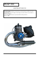
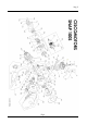
SNAP 100 MAINTENANCE MANUAL All information in this publication is based the lates product information available at the time of approval for printing. CISCOMOTORS reserves the right to make changes at any time without notice and without incurring any obligation. No part of this publication may be reproduced without written permission.
INDEX Pag.2 1. OPERATING INSTRUCTIONS Pag. 3 • 1.1 Basic operation Pag. 4 2. SPECIFICATIONS Pag. 6 • 2.1 Engine installation on chassis • 2.2 Tecnicals characteristics Pag. 6 Pag. 7 3. MAINTENANCE Pag. 8 • 3.1 General service information • 3.2 Routine cleaning • 3.3 Maintenance schedule Pag. 8 Pag. 8 Pag. 9 4. STORAGE Pag. 10 5. SPARE PARTS & EQUIPMENT Pag. 11 • 5.1 Spare parts • 5.2 Equipment Pag. 11 Pag. 12 6. ASSEMBLY/ DISASSEMBLY Pag. 13 • • • • • Pag. 13 Pag. 14 Pag. 20 Pag.
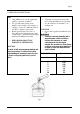
Pag.3 1. OPERATING INSTRUCTIONS FUEL • Snap 100 has a two-stroke engine that requires a gasoline-oil mixture. • Use gasoline with a pump octane number of 92 or higher .if “knocking” or “pinging” occurs, try a different brand of gasoline or a higher octane grade.. • Premix gasoline and oil in a ratio of 40:1. Prepare the fuel mixture in a clean container fig.1 , and shake unitl throughly mixed before filling the fuel tank.
Pag. 4 1.1 BASIC OPERATION • In the 2-stroke motors like the Snap100, is of absolute importance the corrected carburation to avoid seizure to the piston (not covered from guarantee). Start the Engine WARNING • Never run the engine in an enclosed area. The exhaust contains poisonous carbon monoxide gas that can cause loss of consciousness and may lead to death. • Attempting to start the engine without the riducer provokes the outbreak of the clutch and can cause injury or damages.
Pag. 5 Fig.
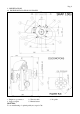
Pag. 6 2. SPECIFICATIONS 2.1 ENGINE INSTALLATION ON CHASSIS Fig.3 1. Engine stop connector 2. Throttle cable 4. Support engine 5. Manual starter CAUTION: To use antivibrating of optimal quality not superior 70s 3.
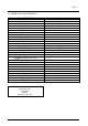
Pag.7 2.2 TECHICALS CHARATTERISTICS Motor SNAP 100S Type Disposition cylinder Bore max Stroke max Displacement Compression ratio Maxim Power Max Torque Lubricating Electrical sistem Ignition Rotor Spark plug standard Winter spark plug Starter Carburettor Type Walbro* Setting screw min Walbro* Setting screw max Trasmission Clutch Type Reduction Reduction ratio Exhaust Type Silencer Support engine Type *The standard carburation Temperature 10°c P 1024 Mb UR 50% Altitude (S.L.M.
Pag. 8 3. MAINTENANCE 3.1 GENERAL SERVICE INFORMATION: • To wear gloves and glances when you make the maintenance; • Do not perform maintenance while engine is running. Injury to your fingers, hands or head may result ; • Perform maintenance on firm, level ground, using hard workstand, and not directly on chassis; • Always install new gaskets, o-rings, piston pin clips, snap rings ect..
Pag. 9 3.3 MAINTENANCE SCHEDULE FREQUENCY INSPECT REPLACE Before and after each use All screw nuts, bolts correctly tigthen, silent-block in. Every 100 hours Cylinder head decarbonizing and cleaning sponge filter Complete piston Every 200 hours Diameter clutch, usury of the bell clutch, and glass wool of the silencer Each year All rubber and plastic components. Crankshaft bearing ,bearing reducer, oil reducer, crankshaft seals, thermical group, connecting rod.
Pag. 10 4. STORAGE Extended storage such as for winter, requires that you take certain steps to reduce the effects of deterioration from nonuse of your Snap100. In addition necessary repairs should be made BEFORE storing your Snap100: otherwise these repairs and clean may be forgotten by the time your Snap100 his removed from storage. .
Pag. 11 5. SPARE PARTS & EQUIPMENT 5.1 SPARE PARTS COD. DESCRIZIONE 000001.0 000002.0 000003.0 000004.0 000005.0 000006.0 000006.1 000006.2 000007.0 000008.0 000009.0 000010.0 000011.0 000012.0 000013.0 000014.0 000015.0 000016.0 000017.0 000018.0 000019.0 000020.0 000021.0 000022.0 000023.0 000024.0 000025.0 000026.0 000027.0 000028.0 000028.1 000028.2 000029.0 000030.0 000030.1 000030.2 000031.0 000032.0 000033.0 000034.0 000035.0 000036.0 000037.0 000038.0 000039.
Pag.12 5.2 EQUIPMENTS COD 100.200 100.201 100.300 100.301 100.302 100.310 100.311 100.312 100.315 100.316 100.320 100.321 100.325 100.
Pag.13 6. DISASSEMBLY/ASSEMBLY WARNING Modification of the motor, or removall of original equipment may make the motor unsafe. 6.1 DISASSEMBLY CARBURETTOR This section covers maintenance of the carburettor. • Repalce diaphragm fuel pump 1. Remove the 4 screw (Fig.4) 2. Remove the diaphragm 3. Clean the filter 4. To replace the diaphragm with a new one. (Fig.5) Fig.4 5. Install the cover and tighten the screw to spefied torque TORQUE: 4Nm (0.4 Kgf/m) Fig.
Pag.14 6.2 DISASSEMBLY TERMICAL GROUP This section covers maintenance of the cylinder and piston. These service can be done with the engine installed in the frame.The cylinder has a nicasil coating and cannot be rebored. If it is demaged, it must be replaced. Before disassembling, clean the engine througly to keep dirt from entering the engine.Remove any gasket material from the mating surfaces. Do not use a screwdriver to remove the cylinder head. Clean all parts before inspecting.
Pag.15 7. Pull the exhaust with resolution (Fig.8) * Apply silicon gasket higt temperature. Fig.8 8. Remove the 4 cylinder head bolts and nuts (Fig.9) Fig.9 9. Remove the cylinder head o-ring gasket (Fig10) Fig.10 NOTE To avoid warping the cylinder head, use a criss-cross pattern to loosen each nut about ¼ turn, then remove the nuts.
Pag.16 DISASSEMBLY PISTON 10. Remove the piston pin clips using a pair of needle-nose pliers (Fig.11) Fig.11 11. Press the piston pin out of the piston and remove the piston.(Fig.12) Fig.12 12. Spread each piston ring end remove by lifting it up a point just oppisite the gap (Fig.13) Fig.13 CAUTION: do not damage the piston ring by spreading the ends too far.
Pag.17 Decarbonizing COMBUSTION CHAMBER Remove the carbon deposits from the combustion chamber. Clean the head gasket surface of any gasket material CAUTION: Use care not to scratch the combustion chamber or the head gasket surface. CYLINDER Clean carbon deposits from the exhaust. CAUTION: Do not damage the cylinder bore. INSTALLATION PISTON 1. Install the piston rings like (Fig.14) 2. Lubricate the piston rings and piston ring grooves with clean 2 stroke oil 3.
Pag18 INSTALLATION CYLINDER 6. Install the new cylinder gasket 7. Allign each ring and gap with the piston ring pins in the ring groves (Fig.16) Fig. 16 8. Lubricate the piston with 2-stroke oil 9. Slip the cylinder over the top of the piston while compressing the rings. (Fig.17) Fig. 17 10.
Pag. 19 INSTALLATION CYLINDER HEAD 1. Install the new cylinder head gasket o-ring (Fig.10) 2. Install the cylinder head and nuts (Fig.9 ), tighten the nuts to the specifed torque. TORQUE : 12Nm( 1,2 kgf/m) NOTE: Tighten the cylinder head nuts in a criss-cross pattern in 2 or 3 steps INSTALLATION EXHAUST 1. Insert the antivibrating pins thread in the support exhaust (Fig. 6) 2. Pull the exhaust with resolution and insert the spherical entrance on the cylinder (Fig. 8 ) 3. Install the springs (Fig.7) 4.
Pag. 20 6.3 DISASSEMBLY/ASSEMBLY STARTER 1. Remove the air duct see the chapter 6.2 2. Remove 4 screw (Fig.18) 3. Remove the bolt (Fig.19) 4. Remove the pulley CAUTION NOT REMOVE THE SPRING (fig.21) 1. Install the pulley and tighten the screw (Fig. 19) to the specified torque TORQUE : 10Nm( 1 kgf/m) Fig.18 2. Insert the starter into the cooling fan with open grafts (Fig.20) 3. Tighten the screw (Fig.18) to the specified torque TORQUE: 6Nm( 0.6 kgf/m) Fig.19 Fig.20 Fig.
Pag. 21 6.4 DISASSEMBLY/ ASSEMBLY SILENCER 1. Remove the exhaust like chapter 6.2 2. Remove the 3 bolts and cap screw fixing silencer (Fig,.22) 3. Remove the glass wool 4. Remove the carbon deposite from the inner pipe using the wire brush 1. Repalce the glass wool 2. Install the new glass wool packing material, opening the incision of the glass wool NOTE : be carefull not to damage the glass wool 3 . Tighten the 3 bolts and cap screw to the specified torque TORQUE : 12Nm( 1,2 kgf/m) Fig.
Pag.22 6.5 DISASSEMBLY/ASSEMBLY SPONGE FILTER 1. Unscrew the filter band (fig.23) 2. Remove the airbox from the motor 3. Remove 4 screw (Fig.24) 4. Remove the sponge filter (Fig.25) Fig.23 5. Cleaning with biodegradable detergents (don’t use gasoline)and dry the sponge filter. 6. Lubricate the sponge filter.(Fig.25) 7. Assembly all of the airbox CAUTION INSTALL THE SECURITY CABLE (fig.23) Fig.24 Fig.
Pag.23 7. CARBURATION REGULATION 1. Regulation throttle cable 2. Regulation Min. gasoline 3. Regulation Max gasoline Fig.26 Standard regulation In case of problems of wrong carburetion , repalce the originals levels. Screw regulation of min. 1/4 turns from all closing. (Fig.26 point 2) Screw regulation max. remove 4/5 turns from all closing. (Fig.26 point 3) Attention the carburation regulation must be made at warm motor. To execute in sequence the below operations: 1. 2. 3. 4. 5.
Pag.24 8. TROUBLESHOOTING 1. THE ENGENE DOES NOT START OR IS HARD TO START CHECK Check if fuel is jetting to the carburettor POSSIBLE CAUSES SOLUTION No fuel in tank Fill tank per fueling Clogget fuel line or fuel filter Replace and clean Diaphragm fuel pomp broken Replace the diaphragm (fig .27) The engine stop switch is to ON Move it on OFF Try spark test Faulty spark plug Replace Broken or shorted inition coil Replace 2.
Pag.25 3. THE ENGINE VIBRATES EXCESSIVE CHECK POSSIBLE CAUSES SOLUTION Exessive wear, holder rubber Repalce (Max 70 Sh) Prop out of balance Balance or replace Silent-block engine 9.