Cisco XR 12000 Series Router SIP and SPA Hardware Installation Guide Cisco IOS XR Release 4.3.0 December 2012 Americas Headquarters Cisco Systems, Inc. 170 West Tasman Drive San Jose, CA 95134-1706 USA http://www.cisco.
THE SPECIFICATIONS AND INFORMATION REGARDING THE PRODUCTS IN THIS MANUAL ARE SUBJECT TO CHANGE WITHOUT NOTICE. ALL STATEMENTS, INFORMATION, AND RECOMMENDATIONS IN THIS MANUAL ARE BELIEVED TO BE ACCURATE BUT ARE PRESENTED WITHOUT WARRANTY OF ANY KIND, EXPRESS OR IMPLIED. USERS MUST TAKE FULL RESPONSIBILITY FOR THEIR APPLICATION OF ANY PRODUCTS.
CONTENTS Preface xvii Changes to This Document Objectives Organization xvii xix xix Related Documentation xx Obtaining Documentation and Submitting a Service Request xx xx CHAPTER 1 Overview: Cisco XR 12000 Series Router SPA Interface Processors SIP and SPA Compatibility 1-1 1-1 Router Hardware Installation 1-2 Supported Platforms 1-3 SIP Summary 1-4 SIP Software and Hardware Compatibility 1-4 Cisco XR 12000 SIP-600 Overview 1-5 Cisco XR 12000 SIP-600 Board Components 1-5 Cisco XR 12000 SIP
Contents Cisco XR 12000 SIP-601 LEDs 1-15 Cisco XR 12000 SIP-601 Physical Specifications 1-16 SPA Subslot Numbering on the Cisco XR 12000 SIP-601 1-16 SPA Interface Addresses on the Cisco XR 12000 SIP-601 1-17 CHAPTER 2 Overview: Cisco XR 12000 Series Router Shared Port Adapters SPA Summary 2-2 Checking Hardware and Software Compatibility Bandwidth Oversubscription 2-1 2-3 2-3 2-Port and 4-Port T3/E3 Serial SPA Overview 2-5 2-Port and 4-Port Clear Channel T3/E3 SPA LEDs 2-5 2-Port and 4-Port Clear C
Contents SFP Module Connections 2-23 SFP Module Cabling and Connection Equipment 2-25 10-Port Gigabit Ethernet SPA Overview 2-26 10-Port Gigabit Ethernet SPA LEDs 2-27 10-Port Gigabit Ethernet SPA Cables and Connectors 2-27 SFP Module Connections 2-27 SFP Module Cabling and Connection Equipment 2-29 1-Port Channelized STM-1/OC-3 SPA Overview 2-30 1-Port Channelized STM-1/OC-3 SPA LEDs 2-30 1-Port Channelized STM-1/OC-3 SPA Interface Specifications 2-31 1-Port Channelized STM-1/OC-3 SPA Cables and Connect
Contents 8-Port OC-3 STM-1/OC-12 STM-4 POS SPA Optical Transceiver Modules and Cables OC-3 Module Connections 2-53 OC-12 Module Connections 2-54 1-Port OC-12/STM-4 POS SPA Overview 2-55 1-Port OC-12/STM-4 POS SPA LEDs 2-55 1-Port OC-12/STM-4 POS SPA Interface Specifications 2-56 1-Port OC-12/STM-4 POS SPA SFP Optical Transceiver Modules and Cables 2-51 2-56 1-Port OC-48/STM-16 POS SPA Overview 2-58 1-Port OC-48/STM-16 POS SPA LEDs 2-58 1-Port OC-48/STM-16 POS SPA Interface Specifications 2-59 1-Port OC-
Contents 24-Port Channelized T1/E1/J1 ATM CEoP SPA Interface Specifications 2-77 24-Port Channelized T1/E1/J1 ATM CEoP SPA Cables and Connectors 2-77 Cable Installation 2-78 SPA Cable Pinouts 2-78 RJ-45 Cable Pinouts 2-81 Patch Panel Cabling 2-81 24-Port Channelized T1/E1/J1 ATM CEoP SPA Patch Panel 2-81 1-Port Channelized OC-3 ATM CEoP SPA Overview 2-82 1-Port Channelized OC-3 ATM CEoP SPA LEDs 2-82 1-Port Channelized OC-3 ATM CEoP SPA Interface Specifications 2-83 1-Port Channelized OC-3 ATM CEoP SPA Opt
Contents CHAPTER 5 Installing and Removing a Shared Port Adapter Handling SPAs 5-1 5-1 Online Insertion and Removal 5-2 SPA Installation and Removal 5-2 Optical Device Installation and Removal Cleaning Optical Devices 5-3 5-3 Checking the Installation 5-4 Verifying the Installation 5-4 Using show Commands to Verify SIP and SPA Status 5-5 Using show Commands to Display SPA Information 5-5 Using the ping Command to Verify Network Connectivity 5-8 CHAPTER 6 Troubleshooting the Installation Troub
Preface Revised: December 2012, OL-17438-04 This preface describes the objectives and organization of this document and explains how to find additional information on related products and services.
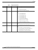
Preface Table 1 Changes to This Document Release No. Revision Date Change Summary 3.6.0 Rev. D1 November 19, 2007 Provides descriptions and installation instructions for the following SPAs: 3.5.1 3.4.1 Rev. C1 Rev.
Preface Table 1 Changes to This Document Release No. Revision Date Change Summary 3.3 Rev. A1 May 15, 2006 Provides descriptions and installation instructions for the following SIPs and SPAs: 3.2 Rev. A0 April 14, 2005 • Cisco XR 12000 SIP-401 • Cisco XR 12000 SIP-501 • Cisco XR 12000 SIP-601 • 2-Port and 4-Port Channelized T3 SPA • 2-Port and 4-Port Clear Channel T3/E3 SPA • 8-Port FastEthernet SPA • 2-Port OC-48 POS/RPR SPA Initial release and 1st publication.
Preface Section Title Description Chapter 5 Installing and Removing a Shared Port Adapter Describes the procedures for installing and removing a SPA on a Cisco 12000 Series Router. It also describes how to verify the SIP and SPA installation. Chapter 6 Troubleshooting the Installation Provides information for troubleshooting the installation of SIPs and SPAs.
CH A P T E R 1 Overview: Cisco XR 12000 Series Router SPA Interface Processors Revised: December 2012, OL-17438-04 This chapter describes the SPA interface processors (SIPs) that are supported on the Cisco XR 12000 Series Router and contains the following sections: • SIP and SPA Compatibility, page 1-1 • Router Hardware Installation, page 1-2 • SIP Software and Hardware Compatibility, page 1-4 • Cisco XR 12000 SIP-600 Overview, page 1-5 • Cisco XR 12000 SIP-401 Overview, page 1-8 • Cisco XR 120
Chapter 1 Overview: Cisco XR 12000 Series Router SPA Interface Processors Router Hardware Installation Table 1-1 SIP and SPA Compatibility on the Cisco XR 12000 Series Router (continued) SPA SIP 401 SIP 501 SIP 601 SIP 600 X X X X X X X 5-Port Gigabit Ethernet SPA 10-Port Gigabit Ethernet SPA 2-Port OC48-POS/RPR SPA X 2-Port and 4-Port OC-48/STM-16 POS SPA X 1-Port OC-192/STM-64 POS/RPR SPA X 4-port OC3/STM1 POS SPA X X X 8-port OC3/STM1 POS SPA X X X 2-port OC12/STM4 POS SPA
Chapter 1 Overview: Cisco XR 12000 Series Router SPA Interface Processors Router Hardware Installation Note References to line cards in the router hardware installation and configuration guides apply equally to SIPs. Supported Platforms SIPs are supported on all Cisco XR 12000 Series Routers. The 2.5G ISE SIP is supported on the Cisco 12016, 124xx, and 128xx routers.
Chapter 1 Overview: Cisco XR 12000 Series Router SPA Interface Processors SIP Summary SIP Summary Summary descriptions of all SIPs supported on the Cisco XR 12000 Series Router are shown in Table 1-2.
Chapter 1 Overview: Cisco XR 12000 Series Router SPA Interface Processors Cisco XR 12000 SIP-600 Overview Table 1-3 SIP SIP Hardware and Software Compatibility Part Number Minimum Cisco IOS XR Software Release Cisco XR 12000 12000-SIP-501 SIP-501 3.3 Cisco XR 12000 12000-SIP-601 SIP-601 3.3 Minimum Hardware Revision The show version and show hardware commands display the current hardware configuration of the router, including the system software version that is currently loaded and running.
Chapter 1 Overview: Cisco XR 12000 Series Router SPA Interface Processors Cisco XR 12000 SIP-600 Overview Cisco XR 12000 SIP-600 LEDs The Cisco XR 12000 SIP-600 supports 2 single-width, double-height SPAs, 2 single-width, single-height SPAs, or 1 dual-width, double-height SPA. The Cisco XR 12000 SIP-600 face plate has one Status LED. Figure 1-2 shows the Cisco 12000 SIP-600 face plate with 2 single-width, single-height SPAs.
Chapter 1 Overview: Cisco XR 12000 Series Router SPA Interface Processors Cisco XR 12000 SIP-600 Overview Figure 1-3 shows a Cisco XR 12000 SIP-600 with 2 SPAs installed. The left SPA slot is subslot 0 and the right SPA slot is subslot 1. If one dual-width SPA is installed, it is recognized as being in subslot 0.
Chapter 1 Overview: Cisco XR 12000 Series Router SPA Interface Processors Cisco XR 12000 SIP-401 Overview Figure 1-4 Slot, Subslot, and Port Locations for the 1-Port 10-Gigabit Ethernet SPA and the 10-Port Gigabit Ethernet SPA.
Chapter 1 Overview: Cisco XR 12000 Series Router SPA Interface Processors Cisco XR 12000 SIP-401 Overview Cisco XR 12000 SIP-401 Board Components The main Cisco XR 12000 SIP-401 board components are shown in Figure 1-5. Figure 1-5 Cisco XR 12000 SIP-401 Board—Rear View 122074 1 2 1 2 SPA enclosure Backplane connector Cisco XR 12000 SIP-401 LEDs The Cisco XR 12000 SIP-401 has two LEDs, as shown in Figure 1-6.
Chapter 1 Overview: Cisco XR 12000 Series Router SPA Interface Processors Cisco XR 12000 SIP-401 Overview Table 1-8 Cisco XR 12000 SIP-401 LED LED Label Color State Meaning Rate Off Off SIP is SIP-401 or SIP-501. Green On SIP is SIP-601. Cisco XR 12000 SIP-401 Physical Specifications The Cisco XR 12000 SIP-401 physical specifications are shown in the following table.
Chapter 1 Overview: Cisco XR 12000 Series Router SPA Interface Processors Cisco XR 12000 SIP-401 Overview 1 SPA subslot 0 3 SPA subslot 2 2 SPA subslot 1 4 SPA subslot 3 SPA Interface Addresses on the Cisco XR 12000 SIP-401 A Cisco 12000 Series Router identifies a SPA interface address by its SIP slot number, SPA subslot, and port number on the SPA, in the format slot/subslot/port. Subslots and ports are numbered starting from 0, so each Cisco XR 12000 SIP-401 has four subslots.
Chapter 1 Overview: Cisco XR 12000 Series Router SPA Interface Processors Cisco XR 12000 SIP-501 Overview Cisco XR 12000 SIP-501 Overview The following sections describe the Cisco XR 12000 SIP-501: • Cisco XR 12000 SIP-501 Board Components, page 1-12 • Cisco XR 12000 SIP-501 LEDs, page 1-12 • Cisco XR 12000 SIP-501 Physical Specifications, page 1-13 • SPA Subslot Numbering on the Cisco XR 12000 SIP-501, page 1-13 • SPA Interface Addresses on the Cisco XR 12000 SIP-501, page 1-14 Cisco XR 12000
Chapter 1 Overview: Cisco XR 12000 Series Router SPA Interface Processors Cisco XR 12000 SIP-501 Overview 1 SPA subslot 0 4 SPA subslot 3 2 SPA subslot 1 5 Ejector Levers 3 SPA subslot 2 6 Status LED The Cisco XR 12000 SIP-501 LEDs are described in Table 1-10. Table 1-10 Cisco XR 12000 SIP-501 LEDs LED Label Color State Meaning Status Yellow On IOS is loaded and SIP is ready to be enabled. Green On SIP is active. Off Off SIP is SIP-401 or SIP-501. Green On SIP is SIP-601.
Chapter 1 Overview: Cisco XR 12000 Series Router SPA Interface Processors Cisco XR 12000 SIP-501 Overview Table 1-12 Subslot Locations for the 1-Port 10-Gigabit Ethernet SPA Call Out Number Description 1 Subslot 0 2 Subslot 1 SPA Interface Addresses on the Cisco XR 12000 SIP-501 A Cisco 12000 Series Router identifies a SPA interface address by its SIP slot number, SPA subslot, and port number on the SPA, in the format slot/subslot/port.
Chapter 1 Overview: Cisco XR 12000 Series Router SPA Interface Processors Cisco XR 12000 SIP-601 Overview Table 1-13 Slot and Port Locations for the 1-Port 10-Gigabit Ethernet SPA Call Out Number Description 1 Slot 3 2 Subslot 0, Port 3/0/0 3 Subslot 1, Ports 3/1/0 to 3/1/9 Cisco XR 12000 SIP-601 Overview The following sections describe the Cisco XR 12000 SIP-601: • Cisco XR 12000 SIP-601 Board Components, page 1-15 • Cisco XR 12000 SIP-601 LEDs, page 1-15 • Cisco XR 12000 SIP-601 Physical
Chapter 1 Overview: Cisco XR 12000 Series Router SPA Interface Processors Cisco XR 12000 SIP-601 Overview Cisco XR 12000 SIP-601 Face Plate 6 0 3 RA TE 2 1 158211 2 ST AT US 1 12000-SIP-400 Figure 1-14 5 3 7 1 SPA subslot 0 5 Ejector Levers 2 SPA subslot 1 6 Status LED 3 SPA subslot 2 7 Rate LED 4 SPA subslot 3 4 5 The Cisco XR 12000 SIP-601 LEDs are described in Table 1-14.
Chapter 1 Overview: Cisco XR 12000 Series Router SPA Interface Processors Cisco XR 12000 SIP-601 Overview Figure 1-15 shows a Cisco XR 12000 SIP-601 with 2 SPAs installed. The left SPA slot is subslot 0 and the right SPA slot is subslot 1. If one dual-width SPA is installed, it is recognized as being in subslot 0.
Chapter 1 Overview: Cisco XR 12000 Series Router SPA Interface Processors Cisco XR 12000 SIP-601 Overview Figure 1-16 Slot, Subslot, and Port Locations for the 1-Port 10-Gigabit Ethernet SPA and the 10-Port Gigabit Ethernet SPA.
CH A P T E R 2 Overview: Cisco XR 12000 Series Router Shared Port Adapters Revised: December 2012, OL-17438-04 This chapter describes the shared port adapters (SPAs) that are supported on the Cisco XR 12000 Series Router and contains the following sections: • SPA Summary, page 2-2 • Bandwidth Oversubscription, page 2-3 • 2-Port and 4-Port T3/E3 Serial SPA Overview, page 2-5 • 2-Port and 4-Port Channelized T3 to DS0 SPA Overview, page 2-7 • 8-Port Channelized T1/E1 SPA Overview, page 2-9 • 8 Por
Chapter 2 Overview: Cisco XR 12000 Series Router Shared Port Adapters SPA Summary • 1-Port and 3-Port Clear Channel OC-3 ATM SPA Overview, page 2-69 • 1-Port Clear Channel OC-12 ATM SPA Overview, page 2-71 • 2-Port Channelized T3/E3 ATM CEoP SPA Overview, page 2-74 • 24-Port Channelized T1/E1/J1 ATM CEoP SPA Overview, page 2-76 • 1-Port Channelized OC-3 ATM CEoP SPA Overview, page 2-82 • 1-Port 10-Gigabit Ethernet DWDM SPA Overview, page 2-83 • 1-Port 10-Gigabit Ethernet WAN PHY SPA Overview
Chapter 2 Overview: Cisco XR 12000 Series Router Shared Port Adapters Bandwidth Oversubscription Table 2-1 Supported SPAs on Cisco XR 12000 Series Routers (continued) Minimum IOS XR Release Minimum Hardware Revision Product Number Description Number of Ports SPA-2XOC48POS 2-Port OC48-POS/RPR SPA 2 3.3.0 1.0 SPA-IPSEC-2G-2 IPSec VPN SPA - 3.4.0 1.0 SPA-1XOC3-ATM-V2 1-Port Clear Channel OC-3 ATM SPA 1 3.7.0 1.0 SPA-3XOC3-ATM-V2 3-Port Clear Channel OC-3 ATM SPA 3 3.7.0 1.
Chapter 2 Overview: Cisco XR 12000 Series Router Shared Port Adapters Bandwidth Oversubscription Note In Cisco IOS XR software release 3.9.1 or prior, the full-rate SPAs need to be positioned in bay 0 and 1. Table 2-2 provides information about the bandwidth for each port (per-port bandwidth) on a SPA, as well as the cumulative bandwidth (total bandwidth) for all ports available on the SPA.
Chapter 2 Overview: Cisco XR 12000 Series Router Shared Port Adapters 2-Port and 4-Port T3/E3 Serial SPA Overview Table 2-2 SPA Bandwidth Capacity (continued) SPA Number Per-Port Bandwidth of Ports Total Bandwidth 1-Port 10-Gigabit Ethernet DWDM SPA 10 Gbps 1 10 Gbps 1-Port 10-Gigabit Ethernet WAN PHY SPA 10 Gbps 1 10 Gbps 1. Total bandwidth value assumes eight OC-12/STM-4 optics modules.
Chapter 2 Overview: Cisco XR 12000 Series Router Shared Port Adapters 2-Port and 4-Port T3/E3 Serial SPA Overview Table 2-3 LED Label A/L STATUS 2-Port and 4-Port Clear Channel T3/E3 SPA LEDs (continued) Color State Meaning Amber On Port is enabled by software, and there is at least one alarm. Off Off Port is not enabled by software. Green On Port is enabled by software, and loopback is off. Amber On Port is enabled by software, and loopback is on. Off Off SPA power is off.
Chapter 2 Overview: Cisco XR 12000 Series Router Shared Port Adapters 2-Port and 4-Port Channelized T3 to DS0 SPA Overview Table 2-4 2-Port and 4-Port Clear Channel T3/E3 SPA Connectors Connector Label Meaning TX Transmitted signals appear on the center contact, and the outer shield is ground for the 75-ohm RG-59 coaxial cable you attach to the TX BNC connector.
Chapter 2 Overview: Cisco XR 12000 Series Router Shared Port Adapters 2-Port and 4-Port Channelized T3 to DS0 SPA Overview The 2-Port and 4-Port Channelized T3 SPA LEDs are described in Table 2-5. Table 2-5 2-Port and 4-Port Channelized T3 SPA LEDs LED Label Color State Meaning C/A Off Off Port is not enabled by software. Green On Port is enabled by software, and there is a valid E3 or T3 signal without any alarms. Amber On Port is enabled by software, and there is at least one alarm.
Chapter 2 Overview: Cisco XR 12000 Series Router Shared Port Adapters 8-Port Channelized T1/E1 SPA Overview Note The Cisco cable part numbers are 72-4124-01 (with Male BNC end) and 72-4131-01 (with Female BNC end). Figure 2-2 shows the Siemax connectors on the 2-Port and 4-Port Channelized T3 SPA, and Table 2-6 provides the signal descriptions for these connectors.
Chapter 2 Overview: Cisco XR 12000 Series Router Shared Port Adapters 8-Port Channelized T1/E1 SPA Overview Table 2-7 8-Port Channelized T1/E1 SPA LEDs LED Label Color State Meaning C/A Off Off Port is not enabled by software. Green On Port is enabled by software, and there is a valid T1 or E1 signal without any alarms. Amber On Port is enabled by software, and there is at least one alarm. Off Off Port is not enabled by software. Green On Port is enabled by software, loopback is off.
Chapter 2 Overview: Cisco XR 12000 Series Router Shared Port Adapters 8 Port FastEthernet SPA Overview Table 2-8 describes the signals and connector pinouts for RJ-45 cable connectors.
Chapter 2 Overview: Cisco XR 12000 Series Router Shared Port Adapters 8 Port FastEthernet SPA Overview Table 2-9 LED Label 8-Port FastEthernet SPA LEDs Color State Meaning Off Port is not enabled. On Port is enabled and the link is up. Amber On Port is enabled and the link is down. Off Off SPA power is off. Green On SPA is ready and operational. Amber On SPA power is on and good, and the SPA is being configured. Port Number Off A/L (0, 1, 2, 3, 4, Green 5, 6 or 7)1 STATUS 1.
Chapter 2 Overview: Cisco XR 12000 Series Router Shared Port Adapters 1 Port 10-Gigabit Ethernet SPA Overview Note Referring to the RJ-45 pinout in Table 2-10, proper common-mode line terminations should be used for the unused Category 5 UTP cable pairs 4/5 and 7/8. Common-mode termination reduces the contributions to electromagnetic interference (EMI) and susceptibility to common-mode sources. Wire pairs 4/5 and 7/8 are actively terminated in the RJ-45 port circuitry in the 8-Port FastEthernet SPA.
Chapter 2 Overview: Cisco XR 12000 Series Router Shared Port Adapters 1 Port 10-Gigabit Ethernet SPA Overview 1-Port 10-Gigabit Ethernet SPA LEDs The 1-Port 10-Gigabit Ethernet SPA has two LEDs, an ACTIVE/LINK LED for the port and a STATUS LED, as shown in Figure 2-9. 1-Port 10-Gigabit Ethernet SPA Faceplate K /LIN 122151 ST AT US Figure 2-9 IVE T AC SPA-1X10GE-L-V2 1 1 2 2 ACTIVE/LINK LED STATUS LED Table 2-11 describes the 1-Port 10-Gigabit Ethernet SPA LEDs.
Chapter 2 Overview: Cisco XR 12000 Series Router Shared Port Adapters 1 Port 10-Gigabit Ethernet SPA Overview Figure 2-10 LC-Type Cable for the XFP Optical Transceiver Modules // RX Note // 84929 // TX The 40-pin connector on the 1-Port 10-Gigabit Ethernet SPA is used for resilient packet ring (RPR) connections. This feature is not supported in Cisco IOS XR Release 4.3.0.
Chapter 2 Overview: Cisco XR 12000 Series Router Shared Port Adapters 1 Port 10-Gigabit Ethernet SPA Overview Table 2-12 XFP Module Specifications for 10-Gigabit Ethernet SPA Specification Description Wavelength (TX) 10GLR SR-1: 1260 nm to 1355 nm 10GER IR-2: 1530 nm to 1565 nm 10GZR LR-2: 1530 nm to 1565 nm 10G-MM-SR: 840 nm to 860 nm Cabling distance (maximum) 10GLR SR-1: 6.2 miles (10 km) 10GER IR-2: 24.
Chapter 2 Overview: Cisco XR 12000 Series Router Shared Port Adapters 2-Port Gigabit Ethernet SPA Overview 2-Port Gigabit Ethernet SPA Overview The following sections describe the version 1 and version 2 of the 2-Port Gigabit Ethernet SPA: • 2-Port Gigabit Ethernet SPA LEDs, page 2-17 • 2-Port Gigabit Ethernet SPA (Version 2) LEDs, page 2-18 • SFP Module Cabling and Connection Equipment, page 2-21 2-Port Gigabit Ethernet SPA LEDs The 2-Port Gigabit Ethernet SPA has two types of LEDs: an A/L LED for
Chapter 2 Overview: Cisco XR 12000 Series Router Shared Port Adapters 2-Port Gigabit Ethernet SPA Overview 2-Port Gigabit Ethernet SPA (Version 2) LEDs The 2-Port Gigabit Ethernet SPA (Version 2) has two types of LEDs: an A/L LED for each port (SFP and RJ45) and a STATUS LED, as shown in Figure 2-13.
Chapter 2 Overview: Cisco XR 12000 Series Router Shared Port Adapters 2-Port Gigabit Ethernet SPA Overview 2-Port Fast Ethernet SPA Cables, Connectors, and Pinouts The interface connectors on the 2-Port Fast Ethernet SPA are two individual RJ-45 receptacles. You can use both the interface connectors simultaneously. Each connection supports IEEE 802.3 and Ethernet 10/100BASE-T interfaces compliant with appropriate standards.
Chapter 2 Overview: Cisco XR 12000 Series Router Shared Port Adapters 2-Port Gigabit Ethernet SPA Overview SFP modules exist for technologies other than Gigabit Ethernet and for products other than the 2-Port Gigabit Ethernet SPA. However, the information in this document pertains only to SFP modules that plug into the 2-Port Gigabit Ethernet SPA ports. The SFP module has a receiver port (RX) and a transmitter port (TX) that compose one optical interface.
Chapter 2 Overview: Cisco XR 12000 Series Router Shared Port Adapters 2-Port Gigabit Ethernet SPA Overview SFP-GE-S Modules The 1000BASE-SX (short wavelength) module operates on standard multimode fiber-optic link spans of up to 500 m on 50/125um MMF and 300 m on 62.5/125um MMF. SFP-GE-L Modules The 1000BASE-LX/LH (long wavelength/long haul) module interfaces fully comply with the IEEE 802.3z 1000BASE-LX standard. However, their higher optical quality allows them to reach 6.
Chapter 2 Overview: Cisco XR 12000 Series Router Shared Port Adapters 5-Port Gigabit Ethernet SPA Overview Table 2-19 SFP Module Port Cabling Specifications SFP Modules Wavelength (nm) SFP-GE-S 850 SFP-GE-L SFP-GE-Z SFP-GE-T 1300 1550 N/A Fiber Type Core Size (micron) Modal Bandwidth (MHz/km) Maximum Cable Distance MMF1 62.5 160 722 ft (220 m) 62.5 200 984 ft (300 m) 50.0 400 1640 ft (500 m) 50.0 500 1804 ft (550 m) 62.5 500 1804 ft (550 m) 50.0 400 1804 ft (550 m) 50.
Chapter 2 Overview: Cisco XR 12000 Series Router Shared Port Adapters 5-Port Gigabit Ethernet SPA Overview 5-Port Gigabit Ethernet SPA LEDs The 5-Port Gigabit Ethernet SPA has two types of LEDs: an A/L LED for each individual port and a STATUS LED for the SPA, as shown in Figure 2-15. 5-Port Gigabit Ethernet SPA Faceplate 1 2 A/L (Active/Link) LED 129106 A/ L A/ L A/ L A/ L L 2 A/ SPA-5X1GE-V2 1 ST AT US Figure 2-15 STATUS LED Table 2-20 describes the 5-Port Gigabit Ethernet SPA LEDs.
Chapter 2 Overview: Cisco XR 12000 Series Router Shared Port Adapters 5-Port Gigabit Ethernet SPA Overview The SFP module has a receiver port (RX) and a transmitter port (TX) that compose one optical interface. Table 2-21 and Table 2-22 provide SFP module information and specifications. Table 2-21 SFP Module Options SFP Module Product Number SFP Module Description SFP-GE-S Short wavelength (1000BASE-SX) Contains a Class 1 laser of 850 nm for 1000BASE-SX (short-wavelength) applications.
Chapter 2 Overview: Cisco XR 12000 Series Router Shared Port Adapters 5-Port Gigabit Ethernet SPA Overview SFP-GE-L Modules The 1000BASE-LX/LH (long-wavelength/long-haul) module interfaces fully comply with the IEEE 802.3z 1000BASE-LX standard. However, their higher optical quality allows them to reach 6.2 miles (10 km) over single-mode fiber (SMF) versus the 3.1 miles (5 km) specified in the standard.
Chapter 2 Overview: Cisco XR 12000 Series Router Shared Port Adapters 10-Port Gigabit Ethernet SPA Overview Table 2-23 SFP Module Port Cabling Specifications SFP Modules Wavelength (nm) SFP-GE-S 850 SFP-GE-L SFP-GE-Z SFP-GE-T 1300 1550 N/A Fiber Type Core Size (micron) Modal Bandwidth (MHz/km) Maximum Cable Distance MMF1 62.5 160 722 ft (220 m) 62.5 200 984 ft (300 m) 50.0 400 1640 ft (500 m) 50.0 500 1804 ft (550 m) 62.5 500 1804 ft (550 m) 50.0 400 1804 ft (550 m) 50.
Chapter 2 Overview: Cisco XR 12000 Series Router Shared Port Adapters 10-Port Gigabit Ethernet SPA Overview 10-Port Gigabit Ethernet SPA LEDs The 10-Port Gigabit Ethernet SPA has two types of LEDs: an A/L LED for each individual port and a STATUS LED for the SPA, as shown in Figure 2-16. Figure 2-16 10-Port Gigabit Ethernet SPA Faceplate 1 1 2 2 A/L (Active/Link) LED STATUS LED Table 2-24 describes the 10-Port Gigabit Ethernet SPA LEDs.
Chapter 2 Overview: Cisco XR 12000 Series Router Shared Port Adapters 10-Port Gigabit Ethernet SPA Overview Note The 10-Port Gigabit Ethernet SPA accepts only the SFP modules listed as supported in this document. An SFP module check is run every time an SFP is inserted into the 10-Port Gigabit Ethernet SPA, and only SFP modules that pass this check can be used by the 10-Port Gigabit Ethernet SPA.
Chapter 2 Overview: Cisco XR 12000 Series Router Shared Port Adapters 10-Port Gigabit Ethernet SPA Overview SFP-GE-L Modules The 1000BASE-LX/LH (long-wavelength/long-haul) module interfaces fully comply with the IEEE 802.3z 1000BASE-LX standard. However, their higher optical quality allows them to reach 6.2 miles (10 km) over single-mode fiber (SMF) versus the 3.1 miles (5 km) specified in the standard.
Chapter 2 Overview: Cisco XR 12000 Series Router Shared Port Adapters 1-Port Channelized STM-1/OC-3 SPA Overview Table 2-27 SFP Module Port Cabling Specifications (continued) SFP Modules Wavelength (nm) SFP-GE-Z 1550 Fiber Type Core Size (micron) Modal Bandwidth (MHz/km) SMF 9/10 — 49.7 miles (80 km) SMF2 8 — 62.1 miles (100 km) Maximum Cable Distance 1. Multimode fiber (MMF) only. 2. Dispersion-shifted single-mode fiber-optic cable.
Chapter 2 Overview: Cisco XR 12000 Series Router Shared Port Adapters 1-Port Channelized STM-1/OC-3 SPA Overview The 1-Port Channelized STM-1/OC-3 SPALEDs are described in Table 2-28. Table 2-28 1-Port Channelized STM-1/OC-3 SPA LEDs LED Label Color State Meaning C/A Off Off Port is not enabled by software. Green On Port is enabled by software, and there is a valid T3 signal without any alarms. Amber On Port is enabled by software, and there is at least one alarm.
Chapter 2 Overview: Cisco XR 12000 Series Router Shared Port Adapters 1-Port Channelized STM-4/OC-12 SPA Overview SFP Optics Module 127158 Figure 2-18 The SFP optical transceiver modules used with the 1-Port Channelized STM-1/OC-3 SPA provide the following optical fiber options: • Multimode—155-Mbps, OC-3/STM-1 optical fiber (SONET STS-3 or SDH STM-1) Use a multimode optical fiber that has a core/cladding diameter of 62.5/125 microns.
Chapter 2 Overview: Cisco XR 12000 Series Router Shared Port Adapters 1-Port Channelized STM-4/OC-12 SPA Overview • 1-Port Channelized STM-4/OC-12 SPA Interface Specifications, page 2-34 • 1-Port Channelized STM-4/OC-12 SPA Cables and Connectors, page 2-34 1-Port Channelized STM-4/OC-12 SPA LEDs The 1-Port Channelized STM-4/OC-12 SPA has two types of LEDs: an A/L LED for each port and a STATUS LED, as shown in Figure 2-20.
Chapter 2 Overview: Cisco XR 12000 Series Router Shared Port Adapters 1-Port Channelized STM-4/OC-12 SPA Overview 1-Port Channelized STM-4/OC-12 SPA Interface Specifications The framer processes incoming and outgoing SONET or SDH frames. The framer operates at OC-12/STM-4 line rates (622.08 Mbps). Packet data is transported with a user-configured encapsulation (such as Point-to-Point Protocol [PPP]) and is mapped into the STS-12/STM-4 frame.
Chapter 2 Overview: Cisco XR 12000 Series Router Shared Port Adapters 1-Port Channelized STM-16/OC-48 SPA Overview The SFP optical transceiver modules used with the 1-Port Channelized STM-4/OC-12 SPA provide the following optical fiber options: • Multimode—622-Mbps, OC-12/STM-4 optical fiber (SONET STS-12 or SDH STM-4) Use a multimode optical fiber that has a core/cladding diameter of 62.5/125 microns.
Chapter 2 Overview: Cisco XR 12000 Series Router Shared Port Adapters 1-Port Channelized STM-16/OC-48 SPA Overview Figure 2-23 1-Port Channelized STM-16/OC-48 SPA Faceplate ST AT US 1 A/ C/ L A 2 3 280920 SPA-1XCHOC48/DS3 1 C/A (Carrier/Alarm) LED 2 A/L (Active Loopback) LED 3 STATUS LED The 1-Port Channelized STM-16/OC-48 SPA LEDs are described in Table 2-30.
Chapter 2 Overview: Cisco XR 12000 Series Router Shared Port Adapters 1-Port Channelized STM-16/OC-48 SPA Overview 1-Port Channelized STM-16/OC-48 SPA Cables and Connectors The 1-Port Channelized STM-16/OC-48 SPA uses a small form-factor pluggable (SFP) optical transceiver module installed in each port for SONET and SDH single-mode and multimode optical fiber connection (see Figure 2-24).
Chapter 2 Overview: Cisco XR 12000 Series Router Shared Port Adapters 1-Port OC-192/STM-64 POS SPA Overview 1-Port OC-192/STM-64 POS SPA Overview The 1-Port OC-192/STM-64 POS/RPR SPA is a double-height SPA that is installed in two SIP subslots. The 1-Port OC-192/STM-64 POS/RPR SPA provides SONET and SDH network connectivity with a bandwidth of 9.95 Gbps. For more information about SPA bandwidth, see the “Bandwidth Oversubscription” section on page 2-2.
Chapter 2 Overview: Cisco XR 12000 Series Router Shared Port Adapters 1-Port OC-192/STM-64 POS SPA Overview The 1-Port OC-192/STM-64 POS/RPR SPA LEDs are described in Table 2-31. Table 2-31 1-Port OC-192/STM-64 POS/RPR SPA LEDs LED Label Color State Meaning WRAP Off Off Port is not in wrap mode. Green On Port is in wrap mode somewhere on the ring. Amber On Port is in wrap mode locally. Off Off Port is not in pass-thru mode. Amber On Port is in pass-thru mode.
Chapter 2 Overview: Cisco XR 12000 Series Router Shared Port Adapters 1-Port OC-192/STM-64 POS SPA Overview • RFC 1213, Management Information Base (MIB) for Network Management of TCP/IP-Based Internets:MIB II 1-Port OC-192/STM-64 POS/RPR SPA Fixed Optical Transceiver, 40-Pin Connector, and Cables The 1-Port OC-192/STM-64 POS/RPR SPA uses fixed optical transceivers, one for receive (RX) and one for transmit (TX), for SONET and SDH connection to the network. In Cisco IOS Release 12.
Chapter 2 Overview: Cisco XR 12000 Series Router Shared Port Adapters 1-Port OC-192 STM-64 POS RPR XFP SPA Overview Figure 2-28 SPA Mate Cables 129198 1 2 1 Note Long length RPR mate cable for single port RPR SPAs (CBL-RPR-OC192-L) 2 Short length RPR mate cable for single port RPR SPAs (CAB-RPR-OC192-S) The RPR mate cable is necessary only when the SPA is to be used in RPR mode. It is not needed in POS mode.
Chapter 2 Overview: Cisco XR 12000 Series Router Shared Port Adapters 1-Port OC-192 STM-64 POS RPR XFP SPA Overview 1-Port OC-192/STM-64 POS/RPR XFP SPA LEDs The 1-Port OC-192/STM-64 POS/RPR XFP SPA has six LEDs, as shown in Figure 2-29.
Chapter 2 Overview: Cisco XR 12000 Series Router Shared Port Adapters 1-Port OC-192 STM-64 POS RPR XFP SPA Overview Table 2-32 1-Port OC-192/STM-64 POS/RPR XFP SPA LEDs (continued) LED Label Color State Meaning ACTIVE Off Off Port is not enabled by software. Green On Port is enabled by software, and loopback is off. Amber On Port is enabled by software, and loopback is on. Off Off SPA power off. Green On SPA is ready and operational.
Chapter 2 Overview: Cisco XR 12000 Series Router Shared Port Adapters 1-Port OC-192 STM-64 POS RPR XFP SPA Overview Figure 2-30 shows the cable type for use with the XFP optical transceiver module on the 1-Port OC-192/STM-64 POS/RPR XFP SPA. Figure 2-30 LC-Type Cable for the XFP Optical Transceiver Modules // RX Note // 84929 // TX The 40-pin connector on the 1-Port OC-192/STM-64 POS/RPR XFP SPA is used for resilient packet ring (RPR) connections.
Chapter 2 Overview: Cisco XR 12000 Series Router Shared Port Adapters 4-Port OC-3/STM-1 POS SPA Overview Mate Interface Cables The 1-Port OC-192/STM-64 POS/RPR XFP SPA supports two mate interface configurations: • Mate between two OC-192 SPAs in the same SIP • Mate between two OC-192 SPAs in adjacent SIPs Two 1-Port OC-192/STM-64 POS/RPR XFP SPAs are connected using a 40–pin connector copper mate cable.
Chapter 2 Overview: Cisco XR 12000 Series Router Shared Port Adapters 4-Port OC-3/STM-1 POS SPA Overview Note When SFP modules are replaced, the SPA interface retains any previously defined configurations. These configurations include settings for IP address, clock source, loopback, Cyclic Redundancy Check (CRC), and POS flags. For more information about SPA bandwidth, see the “Bandwidth Oversubscription” section in this chapter.
Chapter 2 Overview: Cisco XR 12000 Series Router Shared Port Adapters 4-Port OC-3/STM-1 POS SPA Overview Table 2-34 2-Port and 4-Port OC-3/STM-1 POS SPA LEDs (continued) LED Label Color State Meaning STATUS Off Off SPA power is off. Green On SPA is ready and operational. Amber On SPA power is on and good, and the SPA is being configured. 2-Port and 4-Port OC-3/STM-1 POS SPA Interface Specifications The framer processes incoming and outgoing SONET or SDH frames.
Chapter 2 Overview: Cisco XR 12000 Series Router Shared Port Adapters 4-Port OC-3/STM-1 POS SPA Overview SFP Optics Module 127158 Figure 2-33 The SFP optical transceiver modules used with the 2-Port and 4-Port OC-3/STM-1 POS SPA provide the following optical fiber options: • Multimode—155-Mbps, OC-3c/STM-1 optical fiber (SONET STS-3c or SDH STM-1) Use a multimode optical fiber that has a core/cladding diameter of 62.5/125 microns.
Chapter 2 Overview: Cisco XR 12000 Series Router Shared Port Adapters 4-Port OC-3/STM-1 POS SPA Overview OC-3 Module Connections Table 2-35 shows the OC-3 specifications of the optics on the 2-Port and 4-Port OC-3/STM-1 POS SPA. Table 2-35 OC-3 Specifications Specification Description Wavelength OC-3 MM: 1270 nm to 1380 nm OC-3 SR: 1260 nm to 1360 nm OC-3 IR-1: 1261 nm to 1360 nm OC-3 LR-1: 1263 nm to1360 nm OC-3 LR-2: 1480 nm to 1580 nm Cabling distance (maximum) OC-3 MM: 2 km (1.
Chapter 2 Overview: Cisco XR 12000 Series Router Shared Port Adapters 8-Port OC-3 STM-1/OC-12 STM-4 POS SPA Overview 8-Port OC-3 STM-1/OC-12 STM-4 POS SPA Overview The 8-Port OC-3 STM-1/OC-12 STM-4 POS SPA is a single-height SPA that installs into one SIP subslot. The SPA with small form-factor pluggable (SFP) optical transceiver modules provides Optical Carrier Level (OC-n) for SONET and Synchronous Transport Module (STM-n) for SDH network connectivity.
Chapter 2 Overview: Cisco XR 12000 Series Router Shared Port Adapters 8-Port OC-3 STM-1/OC-12 STM-4 POS SPA Overview Table 2-36 describes the 8-Port OC-3 STM-1/OC-12 STM-4 POS SPA LEDs. Table 2-36 8-Port OC-3 STM-1/OC-12 STM-4 POS SPA LEDs LED Label Color State Meaning C/A Off Off SONET controller is shut down. Green On Port is enabled by software, and there is a valid SONET signal without any alarms. Amber On Port is enabled by software, and there is at least one alarm.
Chapter 2 Overview: Cisco XR 12000 Series Router Shared Port Adapters 8-Port OC-3 STM-1/OC-12 STM-4 POS SPA Overview The following OC-12 optical transceiver modules are supported on the 8-Port OC-3 STM-1/OC-12 STM-4 POS SPA: • Multimode (MM) SFP module—SFP-OC12-MM • Short-reach (SR) SFP module—SFP-OC12-SR • Intermediate-reach (IR) SFP module (15 km)—SFP-OC12-IR1 • Long-reach (LR) SFP module (40 km)—SFP-OC12-LR1 • Long-reach (LR) SFP module (80 km)—SFP-OC12-LR2 SFP Optics Module 127158 Figure 2
Chapter 2 Overview: Cisco XR 12000 Series Router Shared Port Adapters 8-Port OC-3 STM-1/OC-12 STM-4 POS SPA Overview Figure 2-37 LC-Type Cable // RX // 84929 // TX OC-3 Module Connections Table 2-37 shows the OC-3 specifications of the optics on the 8-Port OC-3 STM-1/OC-12 STM-4 POS SPA.
Chapter 2 Overview: Cisco XR 12000 Series Router Shared Port Adapters 8-Port OC-3 STM-1/OC-12 STM-4 POS SPA Overview Table 2-37 OC-3 Specifications (continued) Specification Description RX overload OC-3 MM: –5 dBm OC-3 SR: –8 dBm OC-3 IR-1: –8 dBm OC-3 LR-1: –10 dBm OC-3 LR-2: –10 dBm Maximum receiver power damage OC-3 MM: +5 dBm OC-3 SR: +5 dBm OC-3 IR-1: +5 dBm OC-3 LR-1: +5 dBm OC-3 LR-2: +5 dBm OC-12 Module Connections Table 2-38 shows the OC-12 specifications of the optics on the 8-Port OC-3
Chapter 2 Overview: Cisco XR 12000 Series Router Shared Port Adapters 1-Port OC-12/STM-4 POS SPA Overview Table 2-38 OC-12 Specifications (continued) Specification Description RX overload OC-12 MM: –6 dBm OC-12 SR: –8 dBm OC-12 IR-1: –8 dBm OC-12 LR-1: –8 dBm OC-12 LR-2: –8 dBm Maximum receiver power damage OC-12 MM: +5 dBm OC-12 SR: +5 dBm OC-12 IR-1: +5 dBm OC-12 LR-1: +5 dBm OC-12 LR-2: +5 dBm 1-Port OC-12/STM-4 POS SPA Overview The 1-Port OC-12/STM-4 POS SPA is single-height SPA that installs i
Chapter 2 Overview: Cisco XR 12000 Series Router Shared Port Adapters 1-Port OC-12/STM-4 POS SPA Overview 1 C/A (Carrier/Alarm) LED 2 A/L (Active Loopback) LED 3 STATUS LED The 1-Port OC-12/STM-4 POS SPA LEDs are described in Table 2-39. Table 2-39 1-Port OC-12/STM-4 POS SPA LEDs LED Label Color State Meaning C/A Off Off Port is not enabled by software. Green On Port is enabled by software, and there is a valid SONET signal without any alarms.
Chapter 2 Overview: Cisco XR 12000 Series Router Shared Port Adapters 1-Port OC-12/STM-4 POS SPA Overview Cisco Systems qualifies the optics that are approved for use with its SPAs.
Chapter 2 Overview: Cisco XR 12000 Series Router Shared Port Adapters 1-Port OC-48/STM-16 POS SPA Overview Figure 2-40 LC-Type Cable // RX // 84929 // TX 1-Port OC-48/STM-16 POS SPA Overview The 1-Port OC-48/STM-16 POS SPA is a single-height SPA that is installed in a SIP subslot. The 1-Port OC-48/STM-16 POS SPA provides RPR over SONET (IEEE 802.17), SRP over SONET (Cisco Proprietary), and Packet over SONET (POS) network connectivity with a bandwidth of 9.95 Gbps.
Chapter 2 Overview: Cisco XR 12000 Series Router Shared Port Adapters 1-Port OC-48/STM-16 POS SPA Overview Note The WRAP, PASSTHRU, and MATESYNC LEDs apply to the SPA in RPR/SRP mode only. The 1-Port OC-48/STM-16 POS SPA LEDs are described in Table 2-40. Table 2-40 1-Port OC-48/STM-16 POS SPA LEDs LED Label Color State Meaning WRAP Off Off Port is not in wrap mode. Green On Port is in wrap mode somewhere on the ring. Amber On Port is in wrap mode locally.
Chapter 2 Overview: Cisco XR 12000 Series Router Shared Port Adapters 1-Port OC-48/STM-16 POS SPA Overview The 1-Port OC-48/STM-16 POS SPA interface is compliant with the following RFCs: • RFC 1662, PPP in HDLC-like Framing • RFC 2615, PPP over SONET/SDH 1-Port OC-48/STM-16 POS SPA Optical Transceiver Modules, Connectors, and Cables The 1-Port OC-48/STM-16 POS SPA uses a single-mode, 9.95 Gbps, OC-48 optical fiber (SONET STS-48) optical transceiver module for SONET connection to the network.
Chapter 2 Overview: Cisco XR 12000 Series Router Shared Port Adapters 2-Port and 4-Port OC-48/STM-16 POS SPA Overview Figure 2-43 SPA Mate Cables 129198 1 2 1 Note Long length RPR mate cable for single port RPR SPAs (CBL-RPR-OC48-L) 2 Short length RPR mate cable for single port RPR SPAs (CAB-RPR-OC48-S) The RPR mate cable is necessary only when the SPA is to be used in RPR mode. It is not needed in POS mode.
Chapter 2 Overview: Cisco XR 12000 Series Router Shared Port Adapters 2-Port and 4-Port OC-48/STM-16 POS SPA Overview 2-Port and 4-Port OC-48/STM-16 POS SPA LEDs The 2-Port and 4-Port OC-48/STM-16 POS SPA has five types of LEDs: four LEDs for each port on the SPA and one STATUS LED, as shown in Figure 2-44.
Chapter 2 Overview: Cisco XR 12000 Series Router Shared Port Adapters 2-Port and 4-Port OC-48/STM-16 POS SPA Overview Table 2-41 2-Port and 4-Port OC-48/STM-16 POS SPA LEDs (continued) LED Label Color State Meaning STATUS Off Off SPA power is off. Green On SPA is ready and operational. Amber On SPA power is on and good, and the SPA is being configured.
Chapter 2 Overview: Cisco XR 12000 Series Router Shared Port Adapters 2-Port and 4-Port OC-48/STM-16 POS SPA Overview OC-48 Module Connections Table 2-42 shows the OC-48 specifications for use with the 2-Port and 4-Port OC-48/STM-16 POS SPA. Table 2-42 OC-48 Specifications Specification Description Wavelength OC-48 SR: 1266 nm to 1360 nm OC-48 IR-1: 1260 nm to 1360 nm OC-48 LR-2: 1500 nm to 1580 nm Cabling distance (maximum) OC-48 SR: 2 km (1.2 miles) OC-48 IR-1: 15 km (9.
Chapter 2 Overview: Cisco XR 12000 Series Router Shared Port Adapters 2-Port OC-48 POS RPR SPA Overview Figure 2-46 SPA Mate Cables 129198 1 2 1 Long length RPR mate cable for single port RPR SPAs (CBL-RPR-OC192-L) 2 Short length RPR mate cable for single port RPR SPAs (CAB-RPR-OC192-S) 2-Port OC-48 POS RPR SPA Overview The following sections describe the 2-Port OC48-POS/RPR SPA: • 2-Port OC48-POS/RPR SPA LEDs, page 2-65 • 2-Port OC48-POS/RPR SPA Interface Specifications, page 2-67 • 2-Port
Chapter 2 Overview: Cisco XR 12000 Series Router Shared Port Adapters 2-Port OC-48 POS RPR SPA Overview Figure 2-47 2-Port OC48-POS/RPR SPA Faceplate 1 2 S PR T AC T ST AT U PT H CA R SPA-2XOC48-POS/RPR 0 3 4 138086 PR T AC T 1 PT H CA R 5 1 PTH (Pass-Through) LED 4 ACT (Active Loopback) LED 2 PRT (Protect) LED 5 STATUS LED 3 CAR (Carrier/Alarm) LED The 2-Port OC48-POS/RPR SPA LEDs are described in Table 2-43.
Chapter 2 Overview: Cisco XR 12000 Series Router Shared Port Adapters Cisco XR12000 IPSec VPN SPA Overview 2-Port OC48-POS/RPR SPA Interface Specifications The physical layer interface for the 2-Port OC48-POS/RPR SPA is Optical Carrier-48 (OC-48), and the 2-Port OC48-POS/RPR SPA is designed to comply with POS specifications. The 2-Port OC48-POS/RPR SPA provides two 2.488-Gbps network interfaces for all supported platforms.
Chapter 2 Overview: Cisco XR 12000 Series Router Shared Port Adapters Cisco XR12000 IPSec VPN SPA Overview Note that the Cisco XR12000 IPSec VPN SPA (SPA-IPSEC-2G-2) supported on the Cisco XR 12000 Series Router is a different form factor from the IPSec VPN SPA supported on the Cisco 7600 router (SPA-IPSEC-2G-1). Warning Attempting to install a SPA-IPSEC-2G-1 into a Cisco XR 12000 SIP-401, Cisco XR 12000 SIP-501, or a Cisco XR 12000 SIP-601 will result in mounting rail damage.
Chapter 2 Overview: Cisco XR 12000 Series Router Shared Port Adapters 1-Port and 3-Port Clear Channel OC-3 ATM SPA Overview 1-Port and 3-Port Clear Channel OC-3 ATM SPA Overview The 1-Port and 3-Port Clear Channel OC-3 ATM SPA is a single-height SPA that installs into one SIP subslot. The Clear Channel OC-3 ATM SPA with small form-factor pluggable (SFP) optical transceiver modules provides SONET and SDH network connectivity with a per-port bandwidth of 155.52 Mbps.
Chapter 2 Overview: Cisco XR 12000 Series Router Shared Port Adapters 1-Port and 3-Port Clear Channel OC-3 ATM SPA Overview Table 2-45 1-Port and 3-Port Clear Channel OC-3 ATM SPA LEDs (continued) LED Label Color State Meaning Green On Port is enabled by software, and loopback is off. Amber On Port is enabled by software, and loopback is on. Off Off SPA power is off. Amber On SPA power is on and good, and SPA is being configured. Green On SPA is ready and operational.
Chapter 2 Overview: Cisco XR 12000 Series Router Shared Port Adapters 1-Port Clear Channel OC-12 ATM SPA Overview • Single-mode—155-Mbps, OC-3 optical fiber (SONET STS-3c or SDH STM-1) Use a single-mode optical fiber that has a modal-field diameter of 8.7 ± 0.5 microns. (Nominal diameter is approximately 10/125 microns.
Chapter 2 Overview: Cisco XR 12000 Series Router Shared Port Adapters 1-Port Clear Channel OC-12 ATM SPA Overview 1-Port Clear Channel OC-12 ATM SPA Faceplate 2 3 Po rt 0 S A/ C L /A 1 ST AT U Figure 2-53 270703 0 SPA-1XOC12-ATM-V2 1 C/A (Carrier/Alarm) LED 2 A/L (Active Loopback) LED 3 STATUS LED The 1-Port Clear Channel OC-12 ATM SPA LEDs are described in Table 2-46.
Chapter 2 Overview: Cisco XR 12000 Series Router Shared Port Adapters 1-Port Clear Channel OC-12 ATM SPA Overview 1-Port Clear Channel OC-12 ATM SPA Cables and Connectors The 1-Port Clear Channel OC-12 ATM SPA uses a small form-factor pluggable (SFP) optical transceiver module installed in each port for SONET and SDH single-mode and multimode optical fiber connection (see Figure 2-54).
Chapter 2 Overview: Cisco XR 12000 Series Router Shared Port Adapters 2-Port Channelized T3/E3 ATM CEoP SPA Overview Figure 2-55 Duplex Patch Cable with LC-Type Connectors // RX // 84929 // TX 2-Port Channelized T3/E3 ATM CEoP SPA Overview The following sections describe the 2-Port Channelized T3/E3 ATM CEoP SPA: • 2-Port Channelized T3/E3 ATM CEoP SPA LEDs • 2-Port Channelized T3/E3 ATM CEoP SPA Interface Specifications • 2-Port Channelized T3/E3 ATM CEoP SPA Cables and Connectors 2-Port Cha
Chapter 2 Overview: Cisco XR 12000 Series Router Shared Port Adapters 2-Port Channelized T3/E3 ATM CEoP SPA Overview Table 2-47 2-Port Channelized T3/E3 ATM CEoP SPA LEDs LED Label Color State Meaning C/A Off Off Port is not enabled by software. Green On Port is enabled by software. Amber On Port is enabled by software, and there is at least one alarm. Off Off Port is not enabled by software. Green On Port is enabled by software, loopback is off.
Chapter 2 Overview: Cisco XR 12000 Series Router Shared Port Adapters 24-Port Channelized T1/E1/J1 ATM CEoP SPA Overview Note • CAB-T3E3-RF-BNC-M (T3 or E3 Cable, 1.0/2.3 RF to BNC-Male, 10 feet) • CAB-T3E3-RF-BNC-F (T3 or E3 Cable, 1.0/2.3 RF to BNC-Female, 10 feet) • CAB-T3E3-RF-OPEN (T3 or E3 Cable, 1.0/2.3 RF to BNC-Open end, 10 feet) • The Cisco cable part numbers are 72-4124-01 (with male BNC end) and 72-4131-01 (with female BNC end).
Chapter 2 Overview: Cisco XR 12000 Series Router Shared Port Adapters 24-Port Channelized T1/E1/J1 ATM CEoP SPA Overview 1 2 A/C (Alarm/Carrier) LEDs STATUS LED The 24-Port Channelized T1/E1/J1 ATM CEoP SPA LEDs are described in the following table. Table 2-49 24-Port Channelized T1/E1/J1 ATM CEoP SPA LEDs LED Label Color State Meaning STATUS Off Off SPA power is off. Amber On SPA power is on and good, and SPA is being configured. Green On SPA is ready and operational.
Chapter 2 Overview: Cisco XR 12000 Series Router Shared Port Adapters 24-Port Channelized T1/E1/J1 ATM CEoP SPA Overview Cable Installation One end of the cable has a 100-pin connector that plugs into the front of the 24-Port Channelized T1/E1/J1 ATM CEoP SPA. Use the thumbscrews on either side of the connector to secure the cable to the SPA. The other end of the cable has two 50-pin Telco connectors that attach to the rear of a 24-port RJ-45 patch panel.
Chapter 2 Overview: Cisco XR 12000 Series Router Shared Port Adapters 24-Port Channelized T1/E1/J1 ATM CEoP SPA Overview Table 2-50 24-Port Channelized T1/E1/J1 ATM CEoP SPA Cable Connector Pinouts (continued) Subscriber Connector Pins Line Signal SPA TX Cable Lead RX Cable Lead Line 4 TX Tip TX Ring 5 55 4 29 Not connected RX Tip RX Ring 29 79 Not connected 4 29 TX Tip TX Ring 6 56 5 30 Not connected RX Tip RX Ring 30 80 Not connected 5 30 TX Tip TX Ring 7 57 6 31 Not connect
Chapter 2 Overview: Cisco XR 12000 Series Router Shared Port Adapters 24-Port Channelized T1/E1/J1 ATM CEoP SPA Overview Table 2-50 24-Port Channelized T1/E1/J1 ATM CEoP SPA Cable Connector Pinouts (continued) Subscriber Connector Pins Line Signal SPA TX Cable Lead RX Cable Lead Line 14 TX Tip TX Ring 15 65 14 39 Not connected RX Tip RX Ring 39 89 Not connected 14 39 TX Tip TX Ring 16 66 15 40 Not connected RX Tip RX Ring 40 90 Not connected 15 40 TX Tip TX Ring 17 67 16 41 N
Chapter 2 Overview: Cisco XR 12000 Series Router Shared Port Adapters 24-Port Channelized T1/E1/J1 ATM CEoP SPA Overview Table 2-50 24-Port Channelized T1/E1/J1 ATM CEoP SPA Cable Connector Pinouts (continued) Subscriber Connector Pins Line Signal SPA TX Cable Lead RX Cable Lead Line 24 TX Tip TX Ring 25 75 24 49 Not connected RX Tip RX Ring 49 99 Not connected 24 49 RJ-45 Cable Pinouts T1 lines from individual subscribers are attached to RJ-45 connectors on the front of the 24-port patc
Chapter 2 Overview: Cisco XR 12000 Series Router Shared Port Adapters 1-Port Channelized OC-3 ATM CEoP SPA Overview For product support for the patch panel, contact Cisco Engineering Support at SMP Data Communications: • 800-880-7674 (toll free in the U.S.A.) • 828-298-2260 (outside the U.S.A.) • ciscoeng@smpdata.
Chapter 2 Overview: Cisco XR 12000 Series Router Shared Port Adapters 1-Port 10-Gigabit Ethernet DWDM SPA Overview The 1-Port Channelized OC-3 ATM CEoP SPA LEDs are described in the following table. Table 2-51 1-Port Channelized OC-3 ATM CEoP SPA LEDs LED Label Color State Meaning C/A Off Off Port is not enabled by software. Green On Port is enabled by software. Amber On Port is enabled by software, and there is at least one alarm. Off Off Port is not enabled by software.
Chapter 2 Overview: Cisco XR 12000 Series Router Shared Port Adapters 1-Port 10-Gigabit Ethernet DWDM SPA Overview 1-Port 10-Gigabit Ethernet DWDM SPA LEDs The 1-Port 10-Gigabit Ethernet DWDM SPA has three LEDs: an ACTIVE/LINK LED for the port, a CARRIER LED, and a STATUS LED, as shown in this figure.
Chapter 2 Overview: Cisco XR 12000 Series Router Shared Port Adapters 1-Port 10-Gigabit Ethernet WAN PHY SPA Overview Cisco Systems qualifies the optics that are approved for use with its SPAs. As of Cisco IOS Release 12.0(31)S, the above listed XFPs are the only optical transceiver modules qualified for use.Use a single-mode optical fiber that has a modal-field diameter of 8.7 ±0.5 microns (nominal diameter is approximately 10/125 microns) to connect your router to a network.
Chapter 2 Overview: Cisco XR 12000 Series Router Shared Port Adapters 1-Port 10-Gigabit Ethernet WAN PHY SPA Overview 1-Port 10-Gigabit Ethernet SPA Faceplate K /LIN 122151 ST AT U S Figure 2-63 IVE T AC SPA-1X10GE-L-V2 1 1 2 2 ACTIVE/LINK LED STATUS LED Table 2-53 describes the 1-Port 10-Gigabit Ethernet SPA LEDs. The LED behavior applies to both the SPA-1X10GE-L-V2 and the SPA-1X10GE-WL-V2 regardless of the mode of operation.
Chapter 2 Overview: Cisco XR 12000 Series Router Shared Port Adapters 1-Port 10-Gigabit Ethernet WAN PHY SPA Overview Figure 2-64 LC-Type Cable for the XFP Optical Transceiver Modules // RX // 84929 // TX XFP Module Connections The 10GLR, 10GER, and 10GZR XFP modules include an optical transmitter and receiver pair integrated with Clock and Data Recovery (CDR) integrated circuits. The XFP modules provide high-speed serial links at the rate of 10.3125 Gbps (10-Gigabit Ethernet LAN PHY mode) and 9.
Chapter 2 Overview: Cisco XR 12000 Series Router Shared Port Adapters 1-Port 10-Gigabit Ethernet WAN PHY SPA Overview Table 2-54 XFP Module Specifications Specification Description Wavelength (TX) 10GLR SR-1: 1260 nm to 1355 nm 10GER IR-2: 1530 nm to 1565 nm 10GZR LR-2: 1530 nm to 1565 nm Cabling distance (maximum) 10GLR SR-1: 6.2 miles (10 km) 10GER IR-2: 24.
CH A P T E R 3 Preparing to Install a Shared Port Adapter or a SPA Interface Processor Revised: December 2012, OL-17438-04 This chapter describes the general equipment, safety, and site preparation requirements for installing SIPs and SPAs.
Chapter 3 Preparing to Install a Shared Port Adapter or a SPA Interface Processor Safety Guidelines • Do not wear loose clothing, jewelry, or other items that could get caught in the router while working with line cards. • Cisco equipment operates safely when it is used in accordance with its specifications and product usage instructions.
Chapter 3 Preparing to Install a Shared Port Adapter or a SPA Interface Processor Preventing Electrostatic Discharge Figure 3-1 Laser Warning Labels for Single-Mode Port PRODUIT LASER DE CLASSE 1 1 PRODUCTO LASER CLASE 1 H6655 CLASS 1 LASER PRODUCT LASERPRODUKT DER KLASSE 1 Warning Invisible laser radiation may be emitted from the aperture ports of the single-mode products when no fiber cable is connected. Avoid exposure and do not stare into open apertures. Warning Class 1 laser product.
Chapter 3 Preparing to Install a Shared Port Adapter or a SPA Interface Processor Required Tools and Equipment Warning For safety, periodically check the resistance value of the ESD strap. The measurement should be between 1 and 10 megohms.
CH A P T E R 4 Installing and Removing a SPA Interface Processor Revised: December 2012, OL-17438-04 This chapter describes how to install or remove SIPs on the Cisco XR 12000 Series Router. This chapter contains the following sections: • Handling SIPs, page 4-1 • Removing and Installing a SIP, page 4-2 Handling SIPs Each SIP circuit board is mounted to a metal carrier and is sensitive to electrostatic discharge (ESD) damage.
Chapter 4 Installing and Removing a SPA Interface Processor Removing and Installing a SIP Figure 4-1 Handling a SIP 70006 Printed circuit board Metal carrier GND Removing and Installing a SIP The following sections describe the procedures for removing and installing SIPs: Note • Guidelines for SIP Removal and Installation • Removing a SIP • Installing a SIP Some of the procedures in the following sections use illustrations of a Cisco 12012 Router to support the descriptions of removing and
Chapter 4 Installing and Removing a SPA Interface Processor Removing and Installing a SIP Caution • The router may indicate a hardware failure if you do not follow proper procedures. Remove or insert only one SIP at a time. Allow at least 15 seconds for the router to complete the preceding tasks before removing or inserting another SIP. SIPs have two ejector levers to release the card from its backplane connector.
Chapter 4 Installing and Removing a SPA Interface Processor Removing and Installing a SIP Figure 4-2 SIP Removal and Installation 0 R VE IE KT TI RR P AC CA RX 1 0 AL OR OR IC IT MAJ MIN CR R VE IE ELL TI RR C AC CA RX R VE IE KT TI RR P AC CA RX Grasp card carrier to slide card out of slot X AU c ET RES Pivot ejector levers away from card to unseat card 1 OTSL 0 OTSL b T EC EJ Loosen captive screws 0 a NSO 2 CO LE T O/L AC R VE IE KT TI RR P AC CA RX ALARM 1 3 TX LL CO RX R VE I
Chapter 4 Installing and Removing a SPA Interface Processor Removing and Installing a SIP Installing a SIP A SIP slides into almost any available SIP slot and connects directly to the backplane. If you install a new SIP, you must first remove the SIP blank from the available slot. Note Refer to the installation and configuration guide for your router for information on SIP slot types, slot width, and slot location.
Chapter 4 Installing and Removing a SPA Interface Processor Removing and Installing a SIP Caution When you install a SIP, always use the ejector levers to ensure that the card is correctly aligned with the backplane connector, the card connector pins make contact with the backplane in the correct order, and the card is fully seated in the backplane. A card that is only partially seated in the backplane can cause the router to hang and subsequently crash.
CH A P T E R 5 Installing and Removing a Shared Port Adapter Revised: December 2012, OL-17438-04 This chapter describes how to install or remove SPAs on the Cisco XR 12000 Series Router.
Chapter 5 Installing and Removing a Shared Port Adapter Online Insertion and Removal Online Insertion and Removal Cisco XR 12000 Series Router SIPs and SPAs support online insertion and removal (OIR). SPAs can be inserted or removed independently from the SIP. OIR of a SIP with installed SPAs is also supported. SPA Installation and Removal You can install one single-width SPA in an SIP. This section provides step-by-step instructions for removing and installing a SPA in an SIP.
Chapter 5 Installing and Removing a Shared Port Adapter Optical Device Installation and Removal Figure 5-2 SPA Installation and Removal A 73 00 -CC B -PA D R LE LS RIE M AB EL AR AR EN RX C RX C X AL R OIR STATUS 7300 PA CARRIE ATM R C C -P A 730 0-C C-P A 84657 7 3 0 0 -C OIR STATUS 7300 PA CARRIER D R LE LS RIE M AB EL AR AR EN X C X C AL R R RX ATM Optical Device Installation and Removal Any contamination of the fiber connection can cause failure of the component or failure of the
Chapter 5 Installing and Removing a Shared Port Adapter Checking the Installation Checking the Installation This section describes the procedures you can use to verify the SIP and SPA installation, and includes information on the following topics: • Verifying the Installation, page 5-4 • Using show Commands to Verify SIP and SPA Status, page 5-5 • Using show Commands to Verify SIP and SPA Status, page 5-5 Verifying the Installation This section describes how to verify the SIP and SPA installation b
Chapter 5 Installing and Removing a Shared Port Adapter Checking the Installation • If a SIP or SPA is replaced with a module of the same type (as in an OIR or hardware swap), the previous configuration will be reinstated when the SIP or SPA becomes active. • If a SIP or SPA has not been previously installed in the same slot or subslot, then the configuration for all associated interfaces will be empty. Note Step 3 New interfaces are not available until you configure them.
Chapter 5 Installing and Removing a Shared Port Adapter Checking the Installation Table 5-1 Table 5-2 show Commands to Display SPA Information Command Type of Information Provided show running-config The router’s running configuration and interfaces available in the system. show hw-module subslot oir The operational status of all SPAs in the system. show diag SPA type in that slot, number of ports, hardware revision, part number, and EEPROM contents.
Chapter 5 Installing and Removing a Shared Port Adapter Checking the Installation Router# 18:05:25: %LINEPROTO-5-UPDOWN: Line protocol on Interface FastEthernet3/1, changed state to down Use the following procedure to verify that the SIP is installed correctly: Step 1 Observe the console display messages and verify that the system discovers the SIP, while the system reinitializes each interface, as follows: • If you installed a new SIP, the STATUS LED should be on (green).
Chapter 5 Installing and Removing a Shared Port Adapter Checking the Installation Note Step 6 New interfaces are not available until you configure them. If the SIP is a replacement, use the show interfaces type slot-number/port-number command or the show controllers command to verify the status of the SPAs. (See the “Using show Commands to Verify SIP and SPA Status” section on page 5 5.
CH A P T E R 6 Troubleshooting the Installation Revised: December 2012, OL-17438-04 This chapter describes how to troubleshoot the installation of SIPs and SPAs on the Cisco XR 12000 Series Router.
Chapter 6 Troubleshooting the Installation Packing a SIP for Shipment The debug spa command is intended for use by Cisco Systems technical support personnel. Caution Because debugging output is assigned high priority in the CPU process, it can render the system unusable. For this reason, use debug commands only to troubleshoot specific problems or during troubleshooting sessions with Cisco technical support personnel.
Chapter 6 Troubleshooting the Installation Packing a SPA for Shipment Packing a SPA for Shipment This section provides step-by-step instructions for packing a SPA and the cable-management brackets for shipment.
Chapter 6 Troubleshooting the Installation Packing a SPA for Shipment Cisco XR 12000 Series Router SIP and SPA Hardware Installation Guide 6-4 OL-17438-04
GLOSSARY D double height Describes the dimension of a SPA that occupies two, vertically-aligned SIP subslots. F FPD Field-programmable device. General term for any hardware component implemented on router cards that supports separate software upgrades. SIPs and SPAs must have the right FPD version to function properly; an FPD incompatibility will disable all interfaces on the SPA or all SPAs within the SIP. FPD image package An FPD image package is used to upgrade FPD images.
Glossary Cisco XR 12000 Series Router SIP and SPA Hardware Installation Guide GL-6 OL-17438-04
INDEX 2-Port and 4-Port Channelized T3 Serial SPA Numerics Cables and Connectors 10G SIP Interface Specifications interface addressing 1-7, 1-14, 1-17 10-Port Gigabit Ethernet SPA cables and connectors LEDs LEDs 2-26 2-27 LEDs 2-83 1-Port 10-Gigabit Ethernet SPA cables and connectors 2-Port and 4-Port OC-3c/STM-1 ATM SPA 2-84 2-13, 2-83, 2-85 2-14, 2-84, 2-85 2-14, 2-15, 2-87 2-70 2-73 2-72 2-71 LEDs 2-75 2-75 2-74 2-71 Cables and Connectors LEDs Cables and Connectors 2-73 Interf
Index overview installation prerequisites 2-50 24-Port Channelized T1/E1 ATM CEoP SPA cables, connectors, and pinouts LEDs intermediate reach SFP module 2-77, 2-78 2-76, 2-77 patch panel 2-81 RJ-45 cable pinouts 2-67 SFP optical transceiver module 2-57 XFP optical transceiver module 2-60 intermediate-reach 2-81 C SFP optical transceiver module 2-47, 2-51, 2-52, 2-63 XFP optical transceiver module 2-43 IPSec 2-68 IPSec VPN SPA cables LC-type LEDS 2-52 (figure) 2-67 2-68 2-15,
Index optical transceiver modules O 2-43, 2-60 OC-3c/STM-1 POS SPA OC-12c/STM-4 Multirate POS SPA bandwidth cables 2-50 cables 2-51 connectors 2-51 2-51 2-51 OC-12c/STM-4 POS SPA interface specifications 2-55 LEDs 2-56 2-55 5-2 optical transceivers 2-56 optical transceiver modules for 8-Port OC-3c/STM-1 and OC-12c/STM-4 POS SPA 2-51 2-56 for OC-192c/STM-64 POS/RPR SPA OC-192c/STM-64 POS/RPR SPA 40-pin mate connector for OC-3c/STM-1 POS SPA 2-40 organization, document 2-40 2-47 for
Index RFC 1213, Management Information Base (MIB) for Network Management of TCP/IP-Based Internets MIB II 2-40, 2-56 SFP-OC3-MM SFP-OC3-SR 2-39, 2-56 RFC 1662, PPP in HDLC-like Framing RFC 2615, PPP over SONET/SDH 2-63, 2-67 SFP-OC48-LR2 2-39, 2-43, 2-51, 2-56 RFC 2427, Multiprotocol Interconnect over Frame Relay 2-51 SFP-OC48-SR 2-63, 2-67 2-63, 2-67 SFP optical transceiver modules (figure) 2-39, 2-43, 2-47, 2-51 2-48 for OC-12c/STM-4 Multirate POS SPA RPR for OC-3c/STM-1 POS SPA 2-42 m
Index troubleshooting SIP installation 6-1 U Using show Commands to Display Interface Information 5-5 Using show Commands to Verify the VIP4 Status 5-5 Using the ping Command to Verify Network Connectivity 5-8 V Verifying the VIP4 Installation 5-4 X XFP (small form-factor pluggable) optical transceiver modules for OC-192c/STM-64 POS/RPR XFP SPA XFP-10GER-OC192IR 2-14, 2-43, 2-60, 2-84, 2-86 XFP-10GLR-OC192SR 2-14, 2-43, 2-60, 2-84, 2-86 XFP-10GZR-OC192LR 2-14, 2-43, 2-86 XFP module cabling 2-
Index Cisco XR 12000 Series Router SIP and SPA Hardware Installation Guide IN-6 OL-17438-04