
Installation guide

Chapter 1 Product Overview
Supervisor Engines
1-12
Catalyst 6500 Series Switch Module Installation Guide
78-15725-02
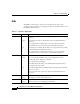
LEDs
The LEDs on the supervisor engine front panel indicate the status of the
supervisor engine, modules, power supplies, and the fan assembly. Table 1-3 lists
the LEDs and their function.
Table 1-3 Supervisor Engine LEDs
LED Color/State Description
STATUS Green All diagnostics pass. The module is operational (normal initialization
sequence).
Orange The module is booting or running diagnostics (normal initialization
sequence).
An overtemperature condition has occurred. (A minor temperature
threshold has been exceeded during environmental monitoring.)
Red The diagnostic test failed. The module is not operational because a fault
occurred during the initialization sequence.
An overtemperature condition has occurred. (A major temperature
threshold has been exceeded during environmental monitoring.)
SYSTEM
1
Green All chassis environmental monitors are reporting OK.
Orange The power supply has failed or the power supply fan has failed.
Incompatible power supplies are installed.
The redundant clock has failed.
One VTT
2
module has failed or the VTT module temperature minor
threshold has been exceeded
3
.
Red Two VTT modules fail or the VTT module temperature major threshold
has been exceeded
3
.
The temperature of the supervisor engine major threshold has been
exceeded.
ACTIVE Green The supervisor engine is operational and active.
Orange The supervisor engine is in standby mode.
PWR MGMT
1
Green Sufficient power is available for all modules.
Orange Sufficient power is not available for all modules.