
Installation guide

B-5
Catalyst 6500 Series Switch Module Installation Guide
78-15725-02
Appendix B Cable and Connector Specifications
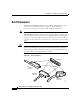
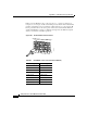
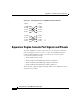
RJ-45 Connector
RJ-45 Connector
The RJ-45 connector is used to connect a Category 3, Category 5, Category 5e, or
Category 6 FTP or UTP cable from the external network to the module interface
connector. (See Figure B-2.) Table B-3 lists the connector pinouts and signal
names for a 10/100BASE-T crossover (MDI-X) cable. Figure B-3 shows a
schematic of the 10/100BASE-T crossover cable. Table B-4 lists the connector
pinouts and signal names for a 1000BASE-T crossover (MDI-X) cable.
Figure B-4 shows a schematic of the 1000BASE-T crossover cable.
Caution Category 5e and Category 6 cables can store high levels of static electricity
because of the dielectric properties of the materials used in their construction.
Always ground the cables (especially in new cable runs) to a suitable and safe
earth ground before connecting them to the module.
Caution To comply with GR-1089 intrabuilding, lightning-immunity requirements, you
must use foil-twisted pair (FTP) cable that is properly grounded at both ends.
99
34
Ring
Tip
21 21
46
Ring
Tip
10 10
35
Ring
Tip
22 22
47
Ring
Tip
11 11
36
Ring
Tip
23 23
48
Ring
Tip
12 12
37
Ring
Tip
24 24
49
Ring
Tip
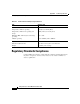
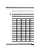
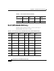
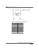
– – – – 25, 50, 51, 52 GND
Table B-2 RJ-21 Connector Pinouts (WS-X6224-FXS Analog Interface Module Only) (continued)
Port
Number
Connector Pin
Number Signal
Port
Number
Connector Pin
Number Signal