
Installation guide

3-7
Catalyst 6500 Series Switch Module Installation Guide
78-15725-02
Chapter 3 Installing the Module
Installing a Supervisor Engine or a Switching Module
supervisor engine or module has not successfully completed the boot process
and may have encountered an error. For more information about the orange
or red STATUS LED states, see the LED table for your specific module in
Chapter 1.
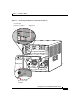
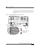
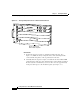
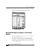
Figure 3-2 Clearing the EMI Gasket in a Horizontal Slot Chassis
1
2
3
FAN
STATUS
4
5
6
S
U
P
E
R
V
IS
O
R
2
W
S
-X
6
K
-S
UP
2-2G
E
STATUS
SYSTEM
CONSOLE
PWR MGMT
RESET
CO
NS
O
LE
CO
N
S
OLE
PO
RT
M
OD
E
P
C
M
C
IA E
JE
C
T
P
OR
T
1
P
O
R
T 2
S
witch Load
100%
1%
LINK
LINK
S
U
P
E
R
V
IS
O
R
2
W
S
-X
6
K
-S
U
P
2
-2G
E
S
T
A
T
U
S
S
Y
S
T
E
M
C
O
N
S
O
L
E
P
W
R
M
G
M
T
R
E
S
E
T
C
O
N
SO
LE
C
O
N
SO
LE
PO
R
T
M
O
D
E
P
C
M
CIA EJE
C
T
P
OR
T 1
P
O
R
T 2
S
w
itch Load
100%
1%
LINK
LINK
1 mm
2
4 P
O
R
T
1
0
0
F
X
W
S-X6224
S
T
A
T
U
S
A
C
T
IV
E
S
E
L
E
C
T
N
E
X
T
4
3
5
5
4
6
6
SWITCH FABIRD MDL
WS-C6500-SFM
S
T
A
T
U
S
A
C
TIV
E
Gap between the module
EMI gasket and the
module above it
Press down
Press down
58570